ZHCSCX7B June 2014 – February 2017 UCD3138128 , UCD3138A64
PRODUCTION DATA.
- 1 特性
- 2 应用范围
- 3 修订历史记录
- 4 说明
- 5 米6体育平台手机版_好二三四系列比较
- 6 Product Feature Overview
- 7 Pin Configuration and Functions
-
8 Specifications
- 8.1 Absolute Maximum Ratings
- 8.2 Handling Ratings
- 8.3 Recommended Operating Conditions
- 8.4 Thermal Information
- 8.5 Electrical Characteristics
- 8.6 Timing Characteristics
- 8.7 PMBUS/SMBUS/IC Timing2
- 8.8 Timing Requirements
- 8.9 Power On Reset (POR) / Brown Out Detect (BOD)
- 8.10 Typical Clock Gating Power Savings
- 8.11 Typical Characteristics
-
9 Detailed Description
- 9.1 Overview
- 9.2 Functional Block Diagram
- 9.3
Feature Description
- 9.3.1 System Module
- 9.3.2 Peripherals
- 9.3.3 Automatic Mode Switching
- 9.3.4 DPWMC, Edge Generation, Intramux
- 9.3.5 Filter
- 9.3.6 Communication Ports
- 9.3.7 Real Time Clock
- 9.3.8 Timers
- 9.3.9 General Purpose ADC12
- 9.3.10 Miscellaneous Analog
- 9.3.11 Brownout
- 9.3.12 Global I/O
- 9.3.13 Temperature Sensor Control
- 9.3.14 I/O Mux Control
- 9.3.15 Current Sharing Control
- 9.3.16 Temperature Reference
- 9.4 Device Functional Modes
- 9.5 Register Maps
- 9.6 Synchronous Rectifier MOSFET Ramp And IDE Calculation
- 10Applications and Implementation
- 11Power Supply Recommendations
- 12Layout
- 13器件和文档支持
- 14机械、封装和可订购信息
12 Layout
12.1 Device Grounding and Layout Guidelines
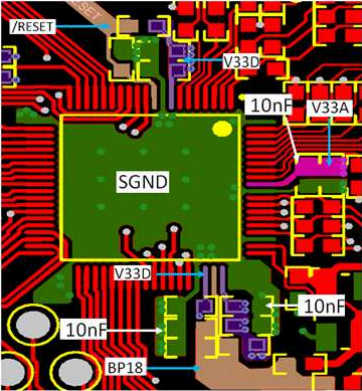
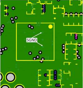
- Single ground is recommended: SGND. A multilayer such as 4 layers board is recommended so that one solid SGND is dedicated for return current path, referred to the layout example.
- Apply multiple different capacitors for different frequency range on decoupling circuits. Each capacitor has different ESL, Capacitance and ESR, and they have different frequency response.
- Avoid long traces close to radiation components, and place them into an internal layer, and it is preferred to have grounding shield.
- Analog circuits and digital circuits should have separate return to ground; although with a single plane, still try to avoid mixing analog current and digital current.
- Do not use a ferrite bead or larger than 3-Ω resistor to connect between V33A and V33D.
- Both 3.3VD and 3.3VA should have local decoupling capacitors close to the device power pins, add vias to connect decoupling caps directly to SGND.
- Avoid negative current/negative voltage on all pins, so Schottky clamping diodes may be needed to limit the voltage; avoid more than 3.8 V or less than –0.3 V voltage spikes on all pins; add Schottky diodes on the pins which could have voltage spikes during surge test; be aware that a Schottky has relatively higher leakage current, which can affect the voltage sensing at high temperature.
- If V33 slew rate is less than 2.5 V/ms the RESET pin should have a 2.21-kΩ resistor between the reset pin and V33D and a 2.2-µF capacitor from RESET to ground. For more details please refer to the UCD3138 Family - Practical Design Guideline. This capacitor must be located close to the device RESET pin.
- RSVD (Pin 61) should be connected to BP18 through 1-kΩ resistor.
- Configure unused GPIO pins to be inputs or connect them to the ground (DGND or SGND); when an external pull-up resistor is used for GPIO, the pull-up resistor needs to be 1 kΩ or higher.
- For more details please refer to the UCD3138 Family - Practical Design Guideline.
12.2 Layout Examples
 Figure 49. Layout Example
 Figure 50. Layout Example