ZHCSFI3B August 2016 – May 2019 UCD90320
PRODUCTION DATA.
- 1 特性
- 2 应用
- 3 说明
- 4 修订历史记录
- 5 说明 (续)
- 6 Pin Configuration and Functions
- 7 Specifications
-
8 Detailed Description
- 8.1 Overview
- 8.2 Functional Block Diagram
- 8.3 Feature Description
- 8.4
Device Functional Modes
- 8.4.1 Rail Monitoring Configuration
- 8.4.2 GPI Configuration
- 8.4.3 Rail Sequence Configuration
- 8.4.4 Fault Responses Configuration
- 8.4.5 GPO Configuration
- 8.4.6 Margining Configuration
- 8.4.7 Pin Selected Rail States Configuration
- 8.4.8 Watchdog Timer
- 8.4.9 System Reset Function
- 8.4.10 Cascading Multiple Devices
- 8.4.11 Rail Monitoring
- 8.4.12 Status Monitoring
- 8.4.13 Data and Error Logging to EEPROM Memory
- 8.4.14 Black Box First Fault Logging
- 8.4.15 PMBus Address Selection
- 8.4.16 ADC Reference
- 8.4.17 Device Reset
- 8.4.18 Brownout
- 8.4.19 Internal Fault Management
- 8.5 Device Configuration and Programming
- 9 Application and Implementation
- 10Power Supply Recommendations
- 11Layout
- 12器件和文档支持
- 13机械、封装和可订购信息
8.4.3 Rail Sequence Configuration
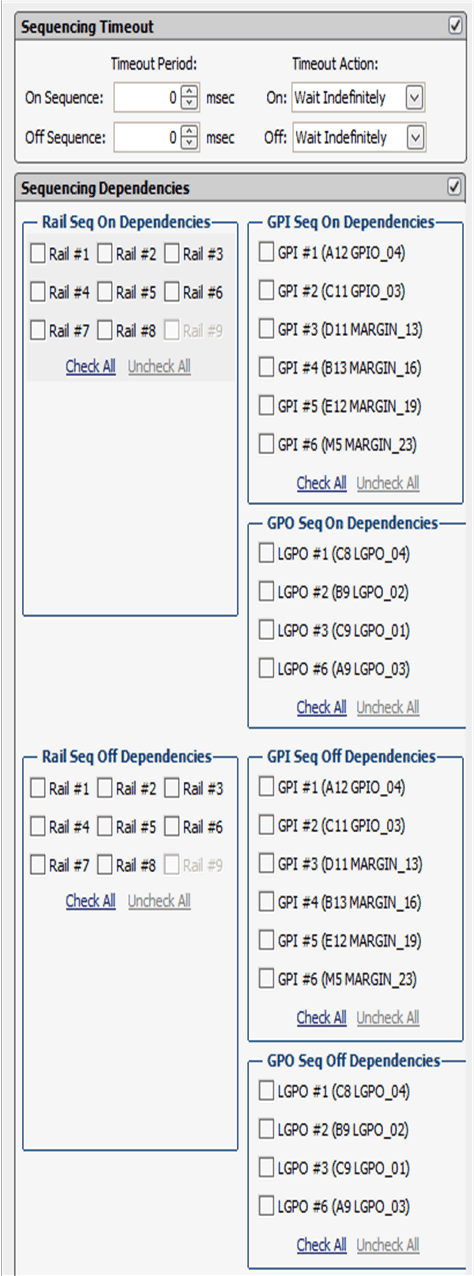
Rail sequences can be configured via the Vout Config tab. First, select a rail in the top-right corner of the Fusion Digital Power Designer software , and then edit the rail sequence as shown in Figure 13.
 Figure 13. Rail Sequence Configuration Window (Rail Config)
 When a rail receives a turn-ON or turn-OFF command as defined in On/Off Config , it checks its dependency conditions. When all dependencies are fulfilled, the rail then waits for a Turn ON Delay time or a Turn OFF Delay time, and then asserts or de-asserts the EN pin.
The device fulfills a Rail Sequence On Dependency status when the rail is in Power Good status. The device fulfills a Rail Sequence Off Dependency status when the rail is in Not Power Good status. The device fulfills a GPI Sequence On Dependency status when the GPI pin is asserted. The device fulfills a GPI Sequence Off Dependency status when the GPI pin is de-asserted. The device fulfills a GPO Sequence On Dependency status when the logical sate of the GPO is TRUE. The device fulfills a GPO Sequence Off Dependency status when the logic state of the GPO is FALSE.
After the EN pin of a rail is asserted, if the rail voltage does not rise above Power Good On threshold within the Maximum Turn-ON time, a Time On Max fault occurs. Similarly, after the EN pin of a rail is de-asserted, if the rail voltage does not fall below 12.5% nominal output voltage within Maximum Turn-OFF time, a Time Off Max warning occurs.
Each rail can include a Fault Shutdown Slaves function. When a rail shuts down as a result of a fault, the associated slave rails also shut down. The device continues to monitor delays and dependencies of the slave rails during the shutdown process. Fault Shutdown Slaves cannot cascade. In other words, if a rail that is acting as a slave shuts down, the associated slave rails does not shut down.
Each rail can set Sequencing On/Off Timeout periods. The timeout periods begin to increment when a rail receives a turn-ON or a turn-OFF command as defined in On/Off Config . When the Sequencing On/Off Timeout period elapsed, the rail executes one of 3 actions including:
- Wait Indefinitely
- Enable or Disable Rail
- Re-sequence (Sequencing On only)
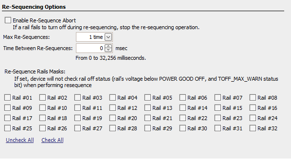
Re-sequence is a series of actions that shuts down a rail and the Fault Shutdown Slaves, and then re-enables the rails according to sequence-on delay times and dependencies. The re-sequencing parameters can be configured in the Other Config tab, as shown in Figure 14.
 Figure 14. Re-Sequencing Options (Global Configuration ► Misc Config)
 A re-sequencing event can be repeated for one to approximately four times or unlimited times. The Time Between Re-Sequences period begins to increment when all the relevant rails are given Not Power Good statuses. When the time period elapses, a re-sequence event begins. When the Enable Re-Sequence Abort is checked, the re-sequence event aborts if any relevant rail triggers a Max Turn Off warning. However, the Max Turn Off warning does not stop an ongoing re-sequence event. If any rails at the re-sequence state are caused by a GPI fault response, the device suspends the entire re-sequence event until the GPI fault is physically clear.
It is also configurable to ignore the POWER_GOOD_OFF and TOFF_MAX_WARN status of a rail when performing re-sequencing if the corresponding bits are set.
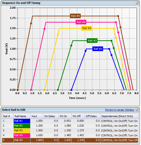
After the Rail Sequence is configured, the GUI displays simulated sequence timing in the Vout Config tab. It demonstrates the dependencies among the rails. An example is shown in Figure 15. The rails power-on and power-off slew rates in Figure 15 are for demonstration purpose only.
 Figure 15. Simulated Sequence Timing Window (Rail Config)