ZHCS846B April 2012 – June 2015 ULN2003LV
PRODUCTION DATA.
8 Application and Implementation
NOTE
Information in the following applications sections is not part of the TI component specification, and TI does not warrant its accuracy or completeness. TI’s customers are responsible for determining suitability of components for their purposes. Customers should validate and test their design implementation to confirm system functionality.
8.1 Application Information
The typical application of the ULN2003LV is a sink driver. The ULN2003LV provides a low-impedance path to GND for driving external peripherals or open-drain signals. If all 7 channels are tied together, the ULN2003 can sink up to 1 A of current in these applications
8.2 Typical Application
To use ULN2003LV as an open-collector or an open-drain inverting logic level shifter configure the device as shown in Figure 7. The ULN2003LV’s each channel input and output logic levels can also be set independently. When using different channel input and output logic voltages connect the ULN2003LV COM pin to the maximum voltage.
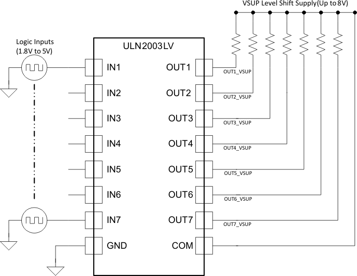 Figure 7. ULN2003LV as Inverting Logic Level Shifter
8.2.1 Design Requirements
ULN2003LV can be used in digital application requiring logic level shifting up to 8 V at the output side. Applications requiring a level shift operation from 1.8 V to 8 V. Since device pulls the output transistor low when input is high, this configuration is useful for applications requiring inverting logic with the level shifting operation.
8.2.2 Detailed Design Procedure
To operate in level shifting operation certain time aspects should be kept in mind. Depending on the pull up resistors at the output ULN2003LV exhibits different propagation delays. The choice of pull up resistor is dependent on the drive required at the output. The device can pull output to ground with the output transistor but to transition from low to high output resistor plays a critical role. If high drive at output is required a lower resistance can be calculated using Equation 1.
For example, a drive of 5 mA is required at the output for 1.8-V to 5-V translation application.
8.2.3 Application Curve
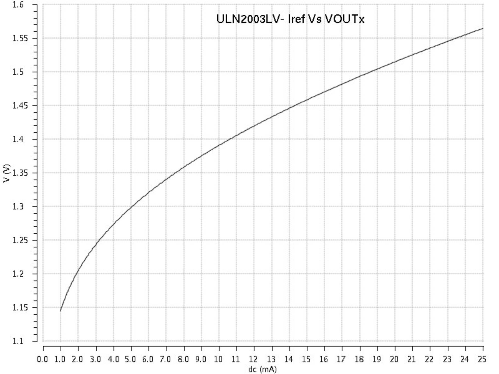 Figure 8. ULN2003LV Iref vs VOUTx
8.3 System Examples
8.3.1 Max Supply Selector
The Figure 9 implements a max supply selector along with a 4-channel logic level shifter using a single ULN20003LV. This setup configures ULN2003LV’s channel clamp diodes OUT5 – OUT7 in a diode-OR configuration and thus the maximum supply among VSUP1, VSUP2 and VSUP3 becomes available at the COM pin. The maximum supply is then used as a pull-up voltage for level shifters. Limit the net GND pin current to less than 100mA DC to ensure reliability of the conducting diode. The unconnected inputs IN5-IN7 are pulled to GND potential through 300kΩ internal pull-down resistor.
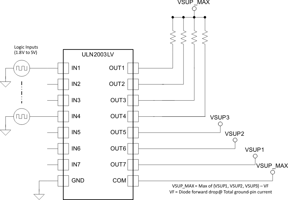 Figure 9. ULN2003LV as Max Supply Selector
8.3.2 Constant Current Generation
When configured as per Figure 10 the ULN2003LV outputs OUT1-OUT6 act as independent constant current sources. The current flowing through the resistor R1 is copied on all other channels. To increase the current sourcing connect several output channels in parallel. To ensure best current copying set voltage drop across connected load such that VOUTx matches to VOUT7.
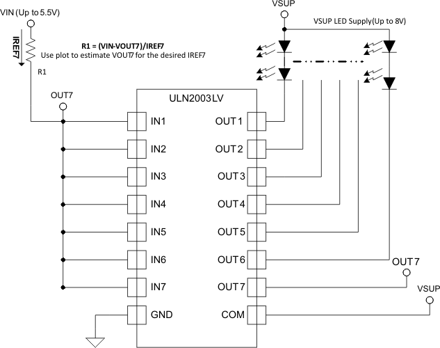 Figure 10. ULN2003LV as a Constant Current Driver
8.3.3 Unipolar Stepper Motor Driver
The Figure 11 shows an implementation of ULN2003LV for driving a uniploar stepper motor. The unconnected input channels can be used for other functions. When an input pin is left open the internal 300kΩ pull down resistor pulls the respective input pin to GND potential. For higher noise immunity use an external short across an unconnected input and GND pins.
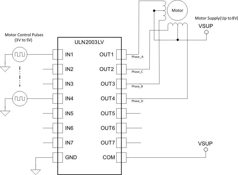 Figure 11. ULN2003LV as a Stepper Motor Driver
8.3.4 NOR Logic Driver
Figure 12 shows a NOR Logic driver implementation using ULN2003LV. The output channels sharing a common pull-up resistor implement a logic NOR of the respective channel inputs. The LEDs connected to outputs OUT5-OUT7 light up when any of the inputs IN5-IN7 is logic-high ( > VIH).
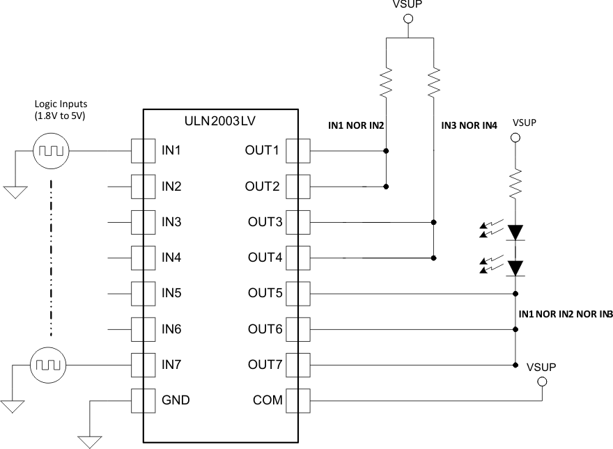 Figure 12. ULN2003LV as a NOR driver
8.3.5 1.8-V Relay Driver
To drive lower voltage relays, like 1.8V, connect two or more adjacent channels in parallel as shown in Figure 13. Connecting several channels in parallel lowers the channel output resistance and thus minimizes VOL for a fixed current.
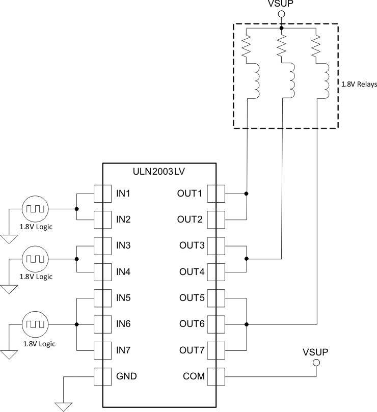 Figure 13. ULN2003LV Driving 1.8V Relays