DLPU107 May 2022 DLP5532-Q1
1.1.2 Illumination Driver PCB
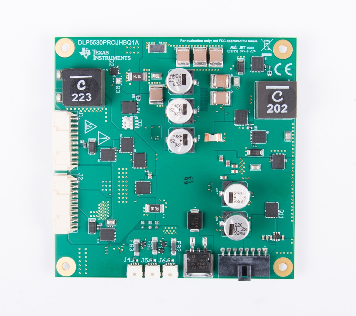
The illumination driver PCB shown in Figure 1-2 is controlled and monitored by the controller PCB over a flex cable. Power can be input to the illumination driver from a bench top supply. The illumination driver provides reverse bias protection and supplies power to the controller PCB over a separate cable. The illumination driver PCB regulates the input power to 17 V prior to the illumination driver circuitry. The illumination driver has outputs for red, green and blue illuminators. These are typically LEDs, but it is possible other illuminators can be used. Together with the controller PCB, the illuminators are meant to be sequentially pulsed and synchronized with the operation of the DMD micromirrors. See Electrical Specifications for input and output specifications of the EVM. Depending on operating conditions, some parts and surfaces of the PCB can be hot.

Hot surface. Contact might cause burns. Do not touch!
 Figure 1-2 DLP5532PROJHBQ1EVM Illumination Driver PCB (Top)
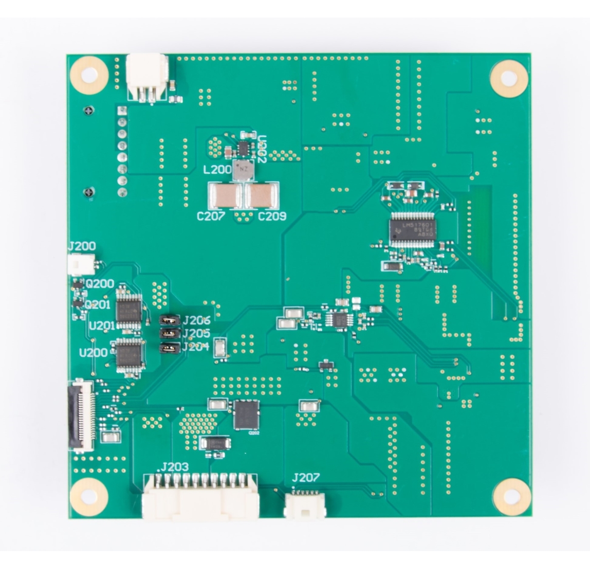
 Figure 1-3 DLP5532PROJHBQ1EVM Illumination Driver PCB (Bottom)
The illumination driver PCB contains the ports listed in Table 1-4. Note that all ports with the schematic reference J20# are located on the bottom of the illumination driver PCB board.
| Schematic Reference | Function |
|---|---|
| J1 | Red Illumination Output - High current output up to 10 A |
| J2 | Green Illumination Output - High current output up to 10 A |
| J3 | Input Power |
| J4 | Fan 1 Power Output |
| J5 | Fan 2 Power Output |
| J6 | Fan 3 Power Output |
| J200 | Fan PWM from Controller |
| J201 | Controller-Driver Control Interface |
| J202 | Controller Power |
| J203 | Blue Illumination Output - High current output up to 10 A |
| J207 | Thermistors for Red, Green, and Blue LEDs |
The illumination driver PCB contains the headers listed in Table 1-5. These headers provide a protective feedback loop between the active cooling fans and the power regulator. In the event that one of the fans is not working or does not receive adequate input power, the feedback loop disables the power regulator and protects the illumination driver circuitry. The headers can be removed to disable the fan feedback loops if fans are not going to be used.
| Header | PIN1 | PIN2 |
|---|---|---|
| J204 | Fan 1 Feedback Signal | EN_UVLO |
| J205 | Fan 2 Feedback Signal | EN_UVLO |
| J206 | Fan 3 Feedback Signal | EN_UVLO |