DLPU110B April   2021  – August 2022 DLPC6540


  1.   Programmer's Guide
  2.   Trademarks
  3. Scope
  4. References
  5. Acronyms
  6. System Boot
    1. 4.1 Data In flash
    2. 4.2 Bootloader Application
    3. 4.3 Main Application
    4. 4.4 Commands supported by Bootloader and Main Applications
    5. 4.5 Debug Terminal
    6. 4.6 HOST_IRQ/SYSTEM_BUSY
    7. 4.7 Heartbeat
    8. 4.8 Low-level Fault
  7. System Status
  8. Version
  9. Power Modes
  10. Display Modes
  11. Source Detection and Configuration
  12. 10Internal sources
    1. 10.1 Test Patterns (TPG)
    2. 10.2 Solid Field (SFG) Color
    3. 10.3 Curtain
  13. 11Display Formatting
  14. 12Image Processing
  15. 13Illumination Control
  16. 14Peripherals
    1. 14.1 GPIO
  17. 15Interface Protocol
    1. 15.1 Supported Interfaces
    2. 15.2 I2C Target
    3. 15.3 USB
  18. 16Command Protocol
    1. 16.1 Command Packet
    2. 16.2 Response Packet
    3. 16.3 Destination Details
    4. 16.4 Error Handling and Recovery
    5. 16.5 System Busy - I2C scenarios
      1. 16.5.1 GPIO implementation
      2. 16.5.2 Short Status response
    6. 16.6 Support for Variable Data Size
  19. 17Auto-Initilization Batch File
  20. 18Command Descriptions
  21. 19 System Commands
    1. 19.1  3D
    2. 19.2  Administrative
    3. 19.3  Autolock
    4. 19.4  Blending
    5. 19.5  Bootloader
    6. 19.6  Calibration
    7. 19.7  Debug Internal
    8. 19.8  Debug
    9. 19.9  General Operation
    10. 19.10 Illumination
    11. 19.11 Image Processing
    12. 19.12 Peripherals
    13. 19.13 Warping
    14. 19.14 Manual WPC
  22. 20Revision History

Scope

This guide provides details of the software interface requirements for a DLPC6540 controller based system. This descriptions includes the communication protocol, initialization, default settings, common use cases and command descriptions.

Figure 1-1 shows a typical projector system using DLPC6540 controller that includes the DLPA3005 power management IC and the .47 4K HSSI DMD.
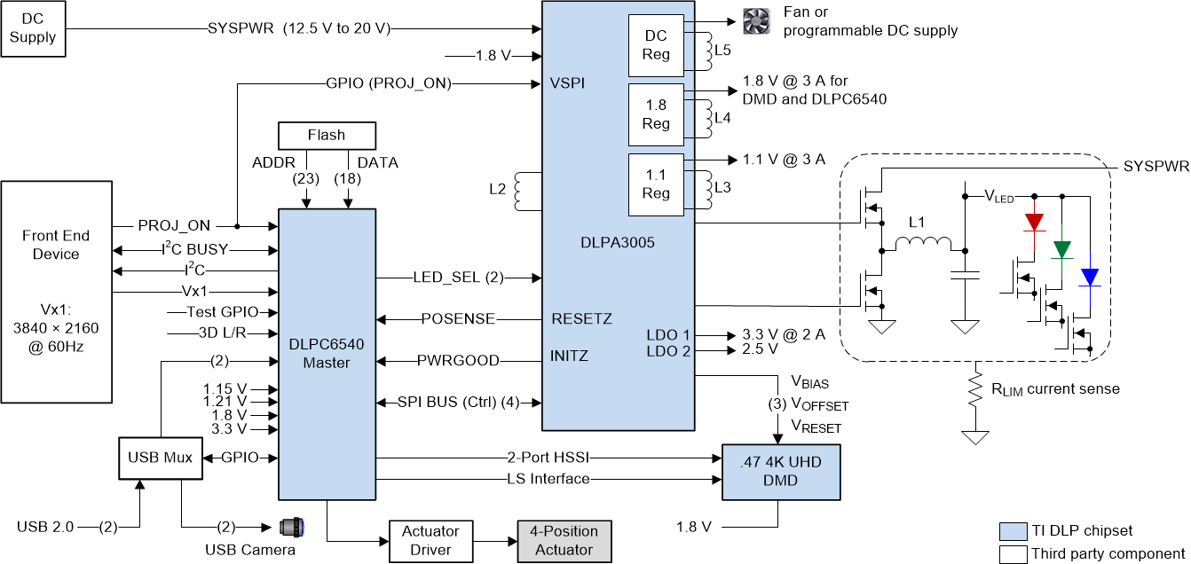
GUID-C353F045-E270-47B1-9310-5CBAB8830223-low.gif Figure 1-1 Typical Projector System Block Diagram