DLPU115 January 2022 DLPC3421
3.1.9.2 Write Parameters
Table 3-5 describes the command parameters.
| Parameter Bytes | Description |
|---|---|
| Byte 1 | TPG pattern select |
| Byte 2 | Foreground and background color (see Table 3-6) |
| Byte 3 | Parameter 1 (see Table 3-7) |
| Byte 4 | Parameter 2 (see Table 3-7) |
| Byte 5 | Parameter 3 (see Table 3-7) |
| Byte 6 | Parameter 4 (see Table 3-7) |
| MSB | Byte 1 | LSB | |||||
|---|---|---|---|---|---|---|---|
| b7 | b6 | b5 | b4 | b3 | b2 | b1 | b0 |
| b(7) | Test pattern border:
|
| b(6:4) | Reserved |
| b(3:0) | Left pattern select:
|
| MSB | Byte 2 | LSB | |||||
|---|---|---|---|---|---|---|---|
| b7 | b6 | b5 | b4 | b3 | b2 | b1 | b0 |
| b(7) | Reserved |
| b(6:4) | Foreground color:
|
| b(3:0) | Reserved |
| b(2:0) | Background color:
|
| Pattern | Byte 2 | |
|---|---|---|
| Foreground Color | Background Color | |
| Solid field | Yes | No |
| Fixed step horizontal ramp | Yes | No |
| Fixed step vertical ramp | Yes | No |
| Horizontal lines | Yes | Yes |
| Vertical lines | Yes | Yes |
| Diagonal lines | Yes | Yes |
| Grid lines | Yes | Yes |
| Checkerboard | Yes | Yes |
| Color bars | No | No |
| Pattern | Byte 6 (Parameter 4) | Byte 5 (Parameter 3) | Byte 4 (Parameter 2) | Byte 3 (Parameter 1) | ||||
|---|---|---|---|---|---|---|---|---|
| Description | Bits | Description | Bits | Description | Bits | Description | Bits | |
| Solid field | N/A | N/A | N/A | N/A | ||||
| Fixed step horizontal ramp | N/A | N/A | End value | 8 | Start value | 8 | ||
| Fixed step vertical ramp | N/A | N/A | End value | 8 | Start value | 8 | ||
| Horizontal lines | N/A | N/A | Background line width | 8 | Foreground line width | 8 | ||
| Vertical lines | N/A | N/A | Background line width | 8 | Foreground line width | 8 | ||
| Diagonal lines | N/A | N/A | Vertical spacing | 8 | Horizontal spacing | 8 | ||
| Grid lines | Vertical background line width | 8 | Vertical foreground line width | 8 | Horizontal background line width | 8 | Horizontal foreground line width | 8 |
| Checkerboard | Number of vertical checkers | 3 | Number of vertical checkers | 8 | Number of horizontal checkers | 3 | Number of horizontal checkers | 8 |
| Color bars | N/A | N/A | N/A | N/A | ||||
This command is used in conjunction with the Write Input Source Select command. This command specifies which test pattern displays when the Write Input Source Select command selects test pattern generator as the image source. The settings for this command are retained until changed using this command. These settings automatically apply each time the test pattern generator is selected.
Batch files are created and stored in flash, and recall the settings for predefined test patterns.
Test patterns are created at the resolution of the display (DMD), are modified by the Write Image Crop command, and displayed at the resolution specified by the Write Display Size command.
Test patterns display at the default frame rate 60 Hz.
The Test Pattern Border Selection creates a white border, a single pixel wide and tall, around the specified test pattern.
The user must review the notes for the Write Input Source Select command to understand the concept of source-associated commands. This concept determines when source-associated commands are executed by the system. This command is a source-associated command.
When a foreground or background color is not used, the bit values are ignored (see Table 3-6). If both foreground and background color are not used, or when a parameter byte (bytes 3 thru 6) is not used, the byte must not be sent. Table 3-8 shows the number of bytes required, based on the specified pattern.
| Specified Pattern | Number of Bytes Required |
|---|---|
| Solid field | 2 |
| Fixed step horizontal ramp | 4 |
| Fixed step vertical ramp | 4 |
| Horizontal lines | 4 |
| Vertical lines | 4 |
| Diagonal lines | 4 |
| Grid lines | 6 |
| Checkerboard | 7 |
| Color bars | 1 |
As noted in Table 3-6, the color for the solid field pattern is specified using the foreground color. An example of a solid field pattern is shown in Figure 3-9.
 Figure 3-9 Example of Solid Field Test Pattern (Red)
As noted in Table 3-6, the color for the fixed step horizontal ramp pattern is specified using the foreground color. As noted in Table 3-7, the user specifies the start value and the stop value for the ramp. For this pattern, the system automatically determines the step size based on the start and stop values and the size of the display (DMD). The minimum start value is 0, the maximum stop value is 255, and the start value must always be smaller than the stop value. For example, if the start value = 0, the stop value = 255, and the DMD resolution is 1280 wide, the step size is 5 (1280 pixels / 256 values = 5). Thus, every gray shade value from 0 to 255 has a step size of 5 pixels (such that each step has 5 columns of pixels with the same gray scale value). The gray scale value always increments by 1 for each step between the start and stop values. An example of a fixed step horizontal ramp pattern is shown in Figure 3-10.
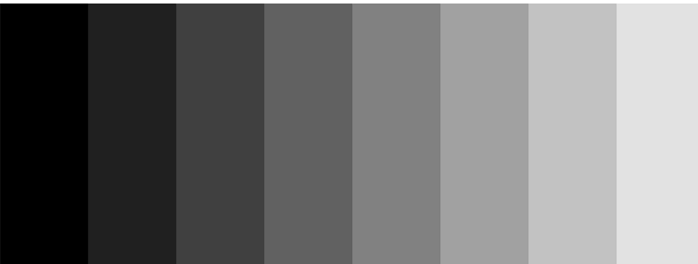 Figure 3-10 Example of Fixed Step Horizontal Ramp Test Pattern
As noted in Table 3-6, the color for the fixed step vertical ramp pattern is specified using the foreground color. As noted in Table 3-7, the user specifies the start value and the stop value for the ramp. For this pattern, the system automatically determines the step size based on the start and stop values and the size of the display (DMD). The minimum start value = 0, the maximum stop value = 255, and the start value must always be smaller than the stop value. For example, if the start value = 0, the stop value = 255, and the DMD resolution is 768 tall, then the step size is 3 (768 pixels / 256 values = 3). Thus, every value from 0 to 255 has a step size of 3 pixels (such that each step has 3 rows of pixels with the same gray scale value). The gray scale value always increments by 1 for each step between the start and stop values. An example of a fixed step vertical ramp pattern is shown in Figure 3-11.
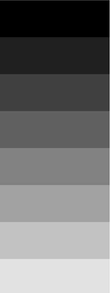 Figure 3-11 Example of Fixed Step Vertical Ramp Test Pattern
As noted in Table 3-6, the colors for the horizontal lines pattern are specified using both the foreground and background colors. The foreground color is used for the horizontal lines, and the background color is used for the space between the lines. As noted in Table 3-7, the user specifies the foreground line width, as well as the background line width. The user must determine the line spacing for each resolution display. For example, if the foreground line width = 1, and the background line width = 9, there is a single pixel horizontal line on every tenth line. An example of a horizontal lines pattern is shown in Figure 3-12.
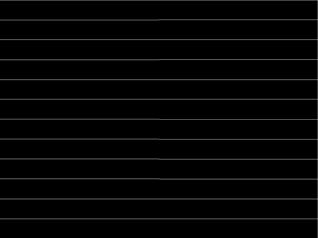 Figure 3-12 Example of Horizontal Lines Test Pattern
As noted in Table 3-6, the colors for the vertical lines pattern are specified using both the foreground and background colors. The foreground color is used for the vertical lines, and the background color is used for the space between the lines. As noted in Table 3-7, the user specifies the foreground line width, as well as the background line width. The user must determine the line spacing for each resolution display. For example, if the foreground line width = 1, and the background line width = 9, there is a single pixel vertical line on every tenth line. An example of a vertical lines pattern is shown in Figure 3-13.
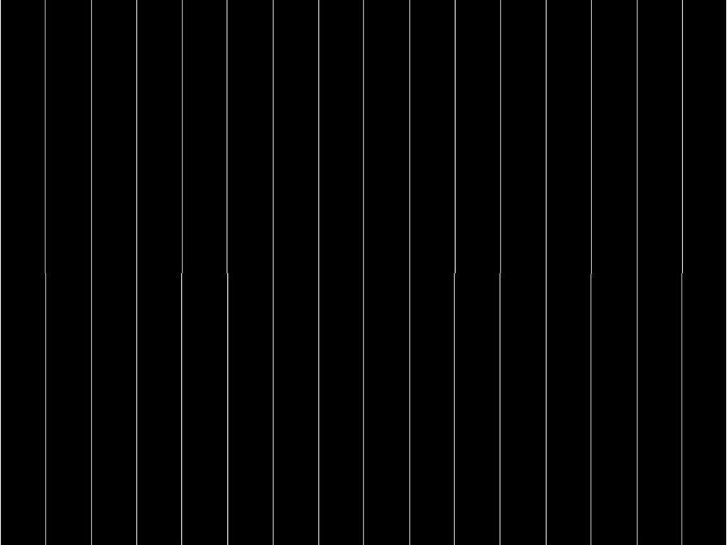 Figure 3-13 Example of Vertical Lines Test Pattern
As noted in Table 3-6, the colors for the diagonal lines pattern are specified using both the foreground and background colors. The foreground color is used for the diagonal lines, and the background color is used for the space between the lines. As noted in Table 3-7, the user specifies the horizontal and vertical line spacing. The line width is always one pixel. The user determines the line spacing for each resolution display. Both horizontal and vertical line spacing must use the same value, and are limited to values of 3, 7, 15, 31, 63, 127, and 255. Invalid values result in a communication error (invalid command parameter). An example of a diagonal lines pattern is shown in Figure 3-14.
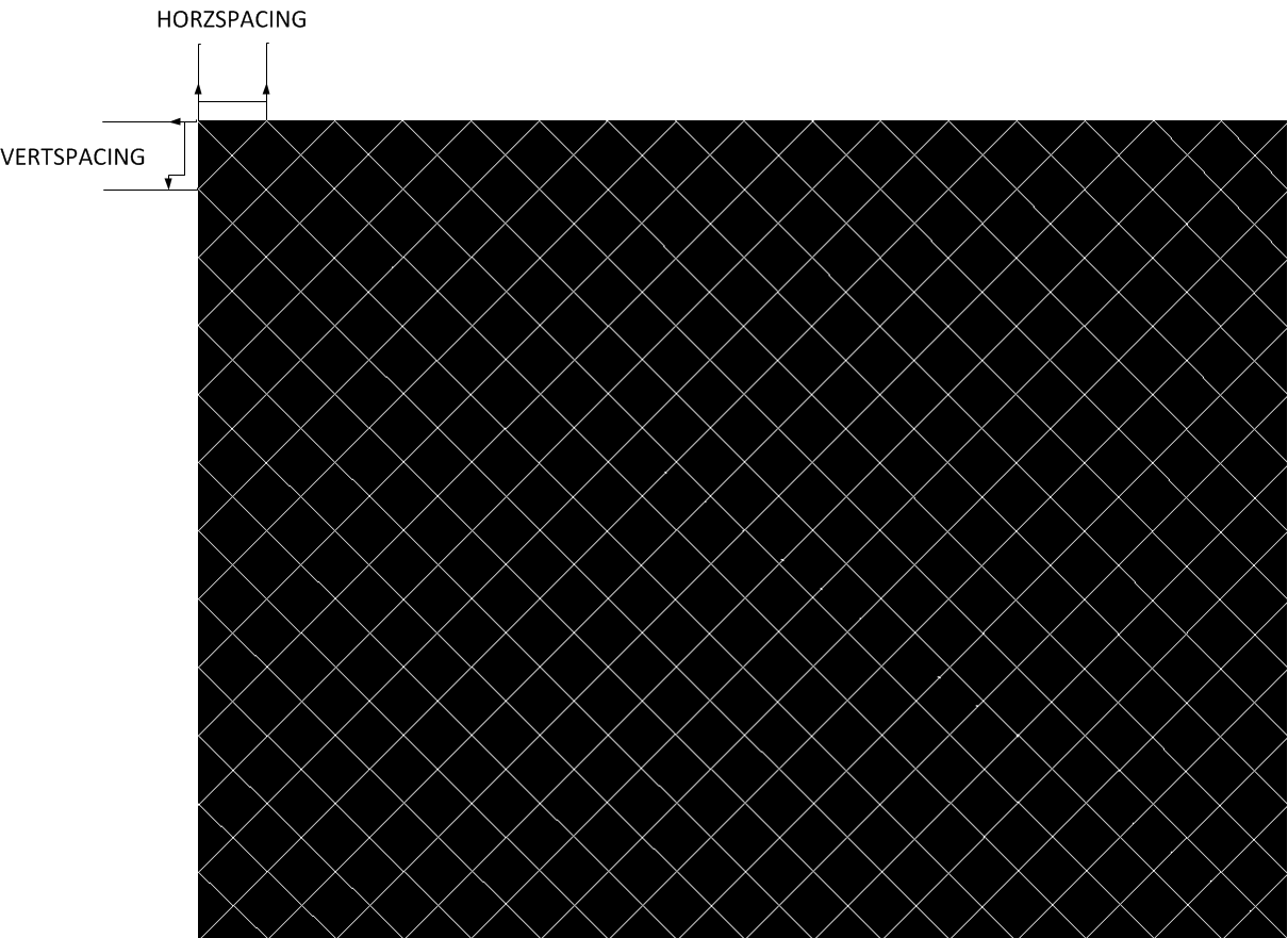 Figure 3-14 Example of Diagonal Lines Test Pattern
As noted in Table 3-6, the colors for the grid lines pattern are specified using both the foreground and background colors. The foreground color is used for the grid lines, and the background color is used for the space between the lines. As noted in Table 3-7, the user specifies the horizontal foreground and background line width, as well as the vertical foreground and background line width. The user determines the line spacing for each resolution display. For example, if the horizontal foreground line width = 1, and background line width = 9, there is a single pixel horizontal line on every tenth line. If the vertical foreground line width = 1, and background line width = 9, there is a single pixel vertical line on every tenth line. An example of a grid lines pattern is shown in Figure 3-15.
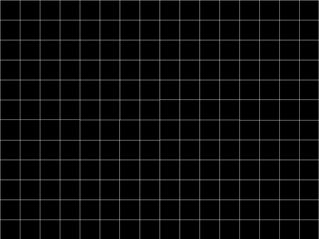 Figure 3-15 Example of Grid Lines Test Pattern
As noted in Table 3-6, the colors for the checkerboard pattern are specified using both the foreground and background colors. The foreground color is used for one of the checkers, and the background color is used for the alternating checker. As noted in Table 3-7, the user specifies the number of horizontal checkers and the number of vertical checkers. For this pattern, the system automatically determines the checker size in each direction based on the number of checkers and the size of the display (DMD). For example, if the number of horizontal checkers = 4, the number of vertical checkers = 4, and the DMD resolution is 1280x720, the size of the horizontal checkers is 320 pixels, and the size of the vertical checkers is 180 pixels (1280 pixels / 4 checkers = 320 pixels: 720 pixels / 4 checkers = 180 pixels). An example of a checkerboard pattern (16 checkers by 12 checkers) is shown in Figure 3-16.
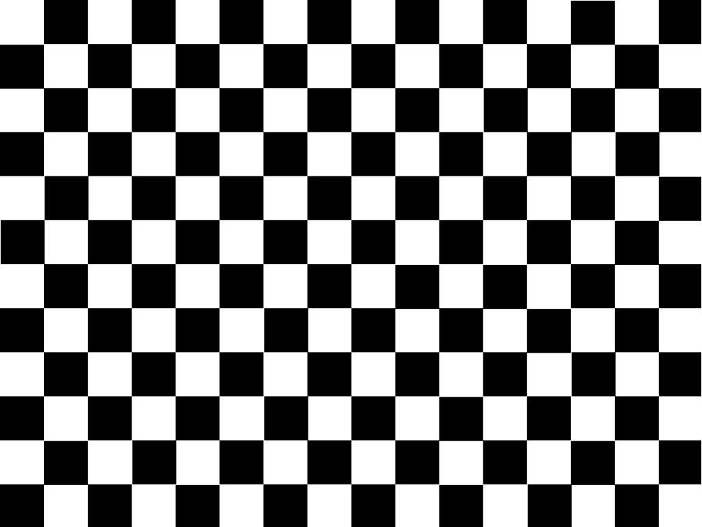 Figure 3-16 Example of Checkerboard Test Pattern
As noted in Table 3-6 and Table 3-7, there is no user programmability associated the color bars test pattern. This pattern is made up of eight vertical color bars: white, yellow, cyan, green, magenta, red, blue, and black. For this pattern, the system automatically determines the width for each color bar based on the size of the display (DMD). An example of the color bars pattern is shown in Figure 3-17.
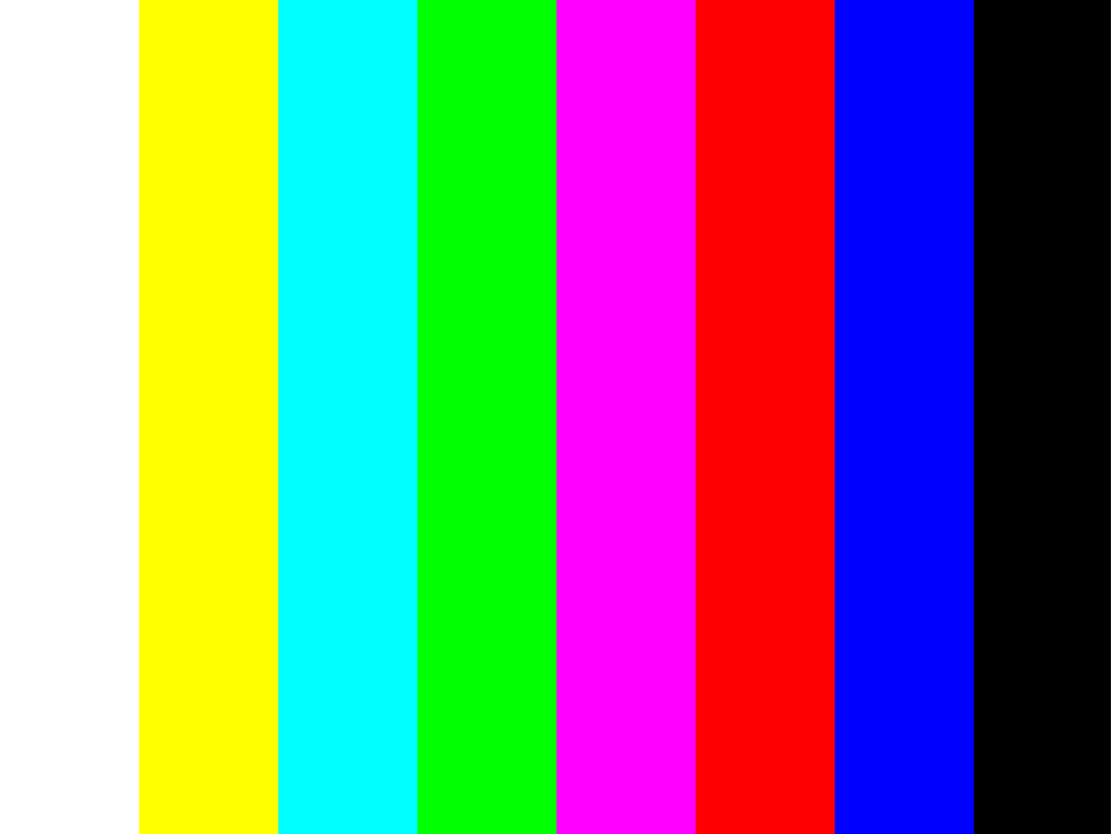 Figure 3-17 Example of Color Bars Test Pattern