DLPU115 January 2022 DLPC3421
3.3.7.2 Write Parameters
Table 3-37 describes the command parameters.
| Parameter Bytes | Description |
|---|---|
| Byte 1 | See Figure 3-53 |
| Byte 2 | Optical throw ratio (LSByte) |
| Byte 3 | Optical throw ratio (MSByte) |
| Byte 4 | Optical DMD offset (LSByte) |
| Byte 5 | Optical DMD offset (MSByte) |
| MSB | Byte 1 | LSB | |||||
|---|---|---|---|---|---|---|---|
| b7 | b6 | b5 | b4 | b3 | b2 | b1 | b0 |
| b(7:1) | Reserved |
| b(0) | Keystone correction enable:
|
Keystone correction digitally compensates for distorted images when the projector is tilted up or down. Keystone correction is specified by the pitch angle (described in the Write Keystone Projection Pitch Angle command) and based on the throw ratio, vertical offset, and projector orientation. Each parameter is provided by this command. With this information, keystone correction corrects for both overall and local area aspect ratio distortion. For both full screen images and sub-images, the full active area of the DMD is keystone-corrected.
When keystone correction is enabled, the Write Border Color command sets the border color to black. Setting this parameter to any other color produces undesirable results.
Image rotation is allowed while keystone correction is enabled, but it may not be appropriate for all situations or configurations. The user is responsible for determining if the result is acceptable.
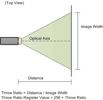
Figure 3-54 shows the bit order and weighting for the optical throw ratio data. Figure 3-55 defines how this data is determined.
| b15 | b14 | b13 | b12 | b11 | b10 | b9 | b8 | b7 | b6 | b5 | b4 | b3 | b2 | b1 | b0 |
|---|---|---|---|---|---|---|---|---|---|---|---|---|---|---|---|
| 27 | 26 | 25 | 24 | 23 | 22 | 21 | 20 | 2–1 | 2–2 | 2–3 | 2–4 | 2–5 | 2–6 | 2–7 | 2–8 |
 Figure 3-55 Visual Definition and Calculation for Optical Throw Ratio Data
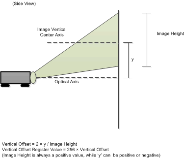
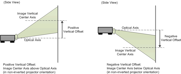
Figure 3-56 shows the bit order and weighting for the two’s complement optical DMD offset data. Figure 3-57 shows how this data is calculated, while Figure 3-58 shows how the sign of the offset data is determined. The user must insure that both the value and the sign of the offset data are correctly determined.
| b15 | b14 | b13 | b12 | b11 | b10 | b9 | b8 | b7 | b6 | b5 | b4 | b3 | b2 | b1 | b0 |
|---|---|---|---|---|---|---|---|---|---|---|---|---|---|---|---|
| 27 | 26 | 25 | 24 | 23 | 22 | 21 | 20 | 2–1 | 2–2 | 2–3 | 2–4 | 2–5 | 2–6 | 2–7 | 2–8 |
 Figure 3-57 Method for Calculation for Optical DMD Offset Data
 Figure 3-58 Sign Determination for Optical DMD Offset Data
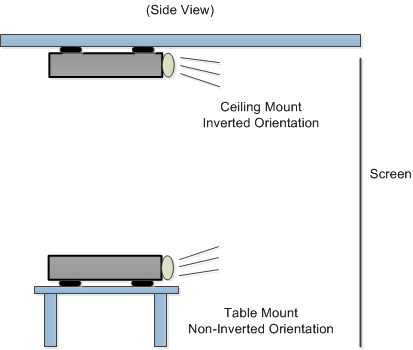
Figure 3-59 shows examples of non-inverted and inverted projector orientation. This information is required for byte 1 of this command.
 Figure 3-59 Examples of Non-Inverted and Inverted Projector Orientations