SBAU171D May 2010 – January 2016 ADS1198 , ADS1298
-
ADS1298ECG-FE/ADS1198ECG-FE
- Trademarks
- 1 ADS1298ECG-FE/ADS1198ECG-FE Overview
- 2 Quick Start
- 3
Using the ADS1298ECG-FE Software
- 3.1 Application User Menu
- 3.2 Top-Level Application Controls
- 3.3 About Tab
- 3.4 ADC Register Tab
- 3.5 Analysis Tab
- 3.6 Save Tab
- 4 ADS1x98ECG-FE Input Signals
- 5 ADS1298ECG-FE/ADS1198ECG-FE Hardware Details
- ASchematics, BOM, Layout, and ECG Cable Details
- BExternal Optional Hardware
- CSoftware Installation
3.2 Top-Level Application Controls
Several controls/indicators are located along the top of the UI screen (see Figure 6). The controls and indicators are described below.
 Figure 6. Top Level Controls
 The Data Rate indicator displays the current data rate of the ADS1298. The data rate can be configured in CONFIG1 control register (see Section 3.4.2.1).
The Progress indicator will display the current progress of data transfer to the PC during acquisition cycles.
The Samples/CH control allows for the selection of the number of points, per channel, to collect during an acquisition cycle. Keep in mind the value entered into this control in relation to the current data rate. Large numbers of samples, coupled with slower data rates, can take time to acquire.
The ACQUIRE control starts the acquisition process. When pressed, the software will collect the requested number of samples from the ADS1298. All points collected during an acquisition process will be contiguous points.
The CONTINUOUS control starts a repeated acquisition process. This function acquires the requested samples and repeats the data acquisition until the button is turned off. Within a single acquisition cycle, the points will be contiguous, but from acquisition to acquisition, there may be points missing.
The Analysis Data input referred checkbox changes the displayed data that is read from the ADC. Checking the box displays the data input referred, while not checking displays the data as converted.
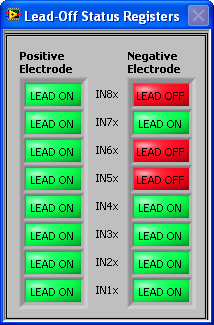
The Show/Poll Lead Off Status displays a window (see Figure 7) that shows the status of the Lead-Off status registers, LOFF STATP and LOFF STATN, of the ADS1298. When the lead for the channel is disconnected, the corresponding channel LED changes from green to red.
 Figure 7. Lead-Off Status Registers Display Window