SBAU279 October 2020 ADS7038-Q1
- Trademarks
- 1Introduction
- 2ADS7038Q1EVM-PDK Overview
- 3ADS7038Q1EVM-PDK Initial Setup
- 4Input Signal-Conditioning Circuitry on the ADS7038Q1EVM
- 5Bill of Materials, Printed Circuit Board Layout, and Schematics
3.3.2.2 Channel Selection
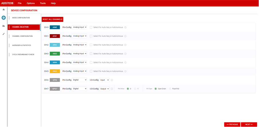
The channel selection configuration option allows the user to configure each of the 8 channels. The default configuration is analog input, but through the drop-down options, each channel can be configured as a digital input or output instead. If using Auto Sequence mode, individual channels can be selected to be included in the sequence, by checking Select for Auto-Seq. The EVM hardware has channel 7 hardwired as a digital output with an LED connected to channel 7 to visually display a high or low digital output state.
To configure for a digital function, change the Pin-Config drop down and select Digital. A second drop-down option will appear in line with the channel, I/O Config. This drop-down option allows to select Input or Output functionality. If output functionality is selected, as shown for channel 7 in Figure 3-6, configuration options will appear in line with the channel. User will be able to select the Pin Value as high or low, and the Pin Type as open drain or push pull. The EVM has an LED connected to channel 7 to display this functionality; changing the Pin Value on channel 7 will turn on or off the LED (D2). As an example to help use the GUI and for Figure 3-6, and throughout the remainder of this document, channel 0 to 5 will be selected as analog inputs, channel 6 as a digital input, and channel 7 as a digital output.
 Figure 3-6 Channel Selection tab.