SBAU321B November 2018 – June 2021 ADS7142 , ADS7142-Q1
3.2 Hardware Setup Instructions
The following are the instructions to set up the BOOSTXL-ADS7142-Q1 for evaluation:
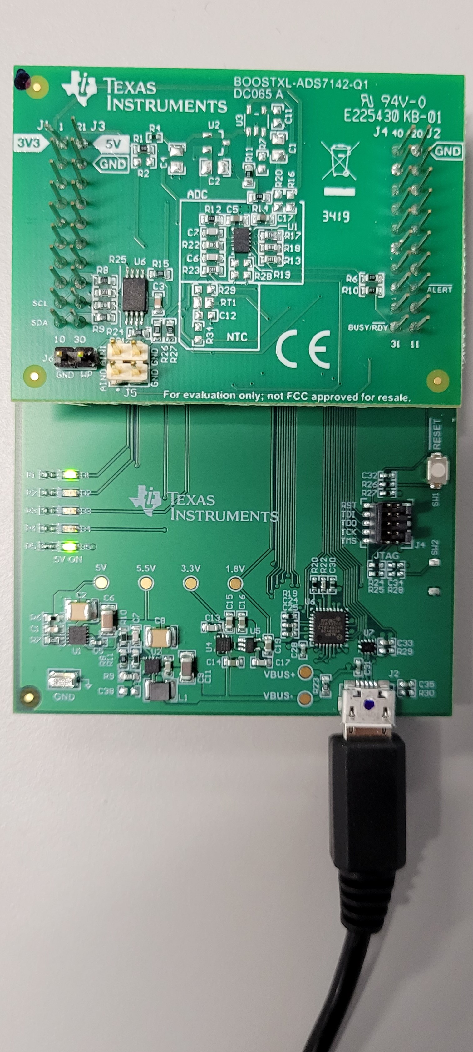
- Stack the BOOSTXL-ADS7142-Q1 on the PAMB. Make sure the 20-pin connector (J1 and J3) on BOOSTXL-ADS7142-Q1 is mapped against the left PAMB connector and the connector (J4 and J2) on BOOSTXL-ADS7142-Q1 is mapped against the right PAMB connector. Pin 1 of BOOSTXL-ADS7142-Q1 must align with pin 1 of left PAMB connector (3V3)
- Connect the micro USB from data port o PAMB to available USB port on PC.
- Figure 3-2 shows the
assembled BOOSTXL-ADS7142-Q1 and PAMB configuration.
 Figure 3-2 BOOSTXL-ADS7142-Q1
Stacked on PAMBoard