SBOA558 November 2022 LMH6642 , LMH6643 , LMH6643Q-Q1 , LMH6644 , OPA2328 , OPA328
4 1-GΩ Transimpedance Amplifier(TIA) Using OPAx328
The wide gain-bandwidth, low input bias current and low input voltage/current noise make the OPAx328 an excellent choice for implementation of the high gain transimpedance amplifier. However, photodiode junction capacitance, Cj, together with the desired trans-impedance gain, total output noise and bandwidth are important factors to be considered before deciding what circuit topology to use, see Figure 4-1.
 Figure 4-1 1-GΩ TIA Options Using OPAx328
The simplest implementation of the transimpedance amplifier may be accomplished by use of a single feedback resistor (RG) to set its gain. However, 1-GΩ gain requires RG of 1 GΩ, which may not be practical because it could be higher than the parallel impedance of photodiode itself resulting in high gain error. Assuming photodiode impedance is much higher than 1-GΩ, you still need to make sure that the application circuit is stable. Since (Cj+Cin)||RG form a zero in 1/beta at , it must be flatten with a pole before intersecting AOL, see Figure 4-2. Selecting CF of 1 pF forms a pole in transimpedance gain limiting the bandwidth to 159 Hz, . This results in the phase margin of 89 degrees whereas the minimum 45 degrees is needed to assure stable operation of the circuit over process variation.
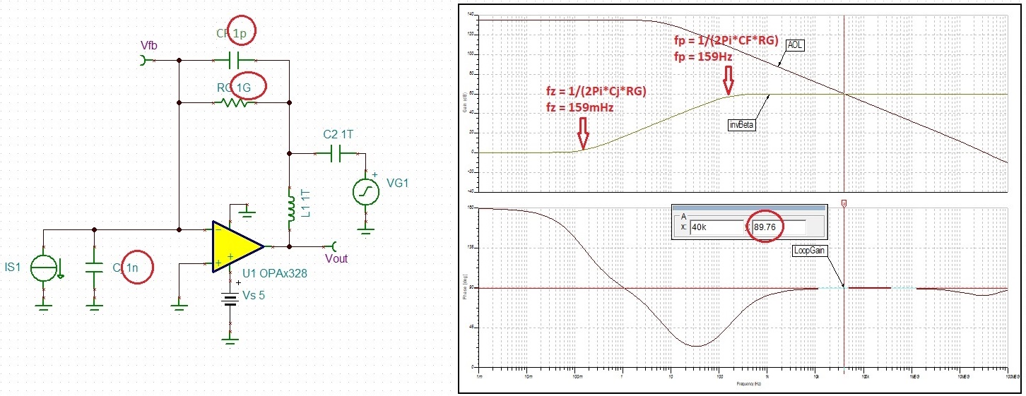 Figure 4-2 1-GΩ TIA AC Stability Using OPAx328
Performing a small-signal transient simulation shows overshoot of just few percent, see Figure 4-3. This confirms a very stable operation of the 1-GΩ TIA.
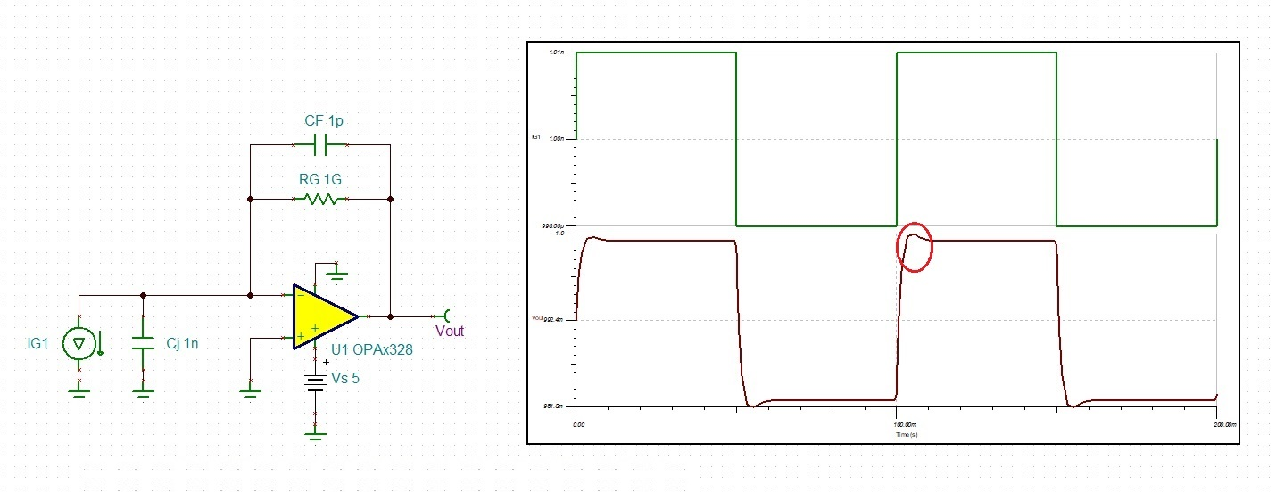 Figure 4-3 1-GΩ TIA Transient Stability Using OPAx328
If the photodiode impedance is lower than 1-GΩ but much higher than 1-MΩ, one may implement the 1-GΩ transimpedance gain as a composite of 1-MΩ RG and an additional inner-loop gain of 1,000-V/V (R2/R1), as Figure 4-4 shows. However, using RG of 1-MΩ together with Cj of 1 nF forms a zero, Thus, as was the case in Figure 4-2, in order to assure stability one must add CF to flatten the 1/beta before intersecting AOL. Adding CF of 100 pF creates a pole at 1,592 Hz, , resulting in 70 degrees phase margin, Figure 4-4. This also leads to the increase of the TIA effective bandwidth by one-order of magnitude.
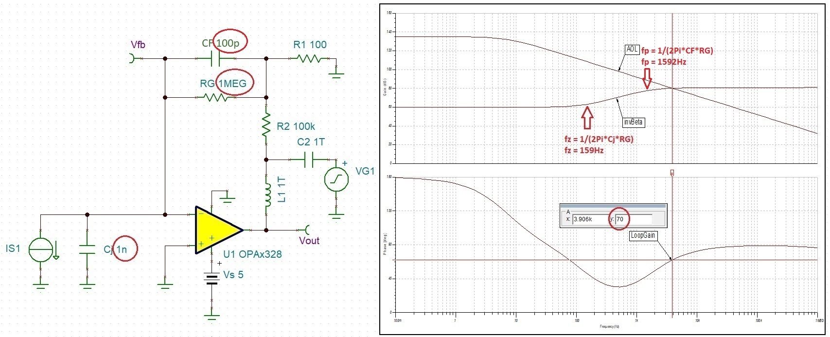 Figure 4-4 1-GΩ TIA in Noise Gain of 1000 AC Stability Using OPAx328
Conducting a small-signal transient analysis shows overshoot of just 10 percent, which confirms stable operation of the composite 1-GΩ transimpedance amplifier, see Figure 4-5.
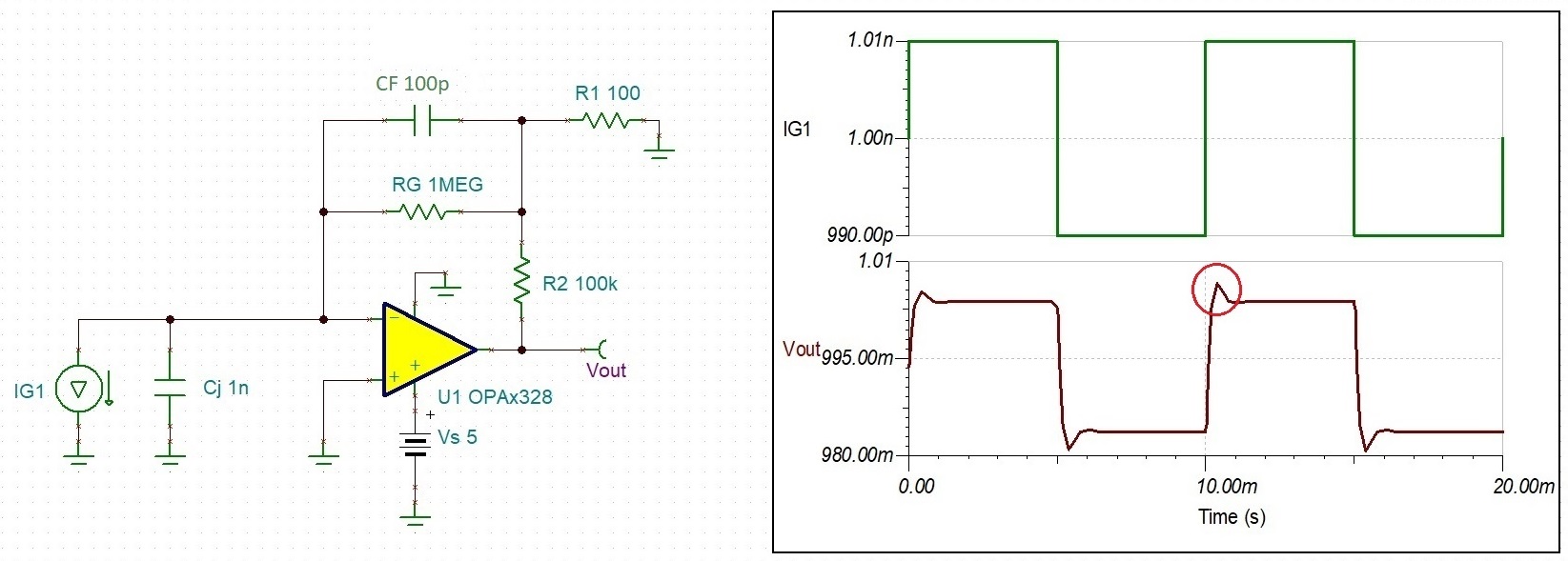 Figure 4-5 1-GΩ TIA (in Noise Gain of 1000) Transient Stability Using OPAx328
Since the implementations of the previously-documented composite 1-GΩ TIA results in vastly higher voltage noise gain and bandwidth than the approach taken in Figure 4-3, this significantly increases the total output noise, which must be taken into consideration to arrive at the most optimal solution - see Figure 4-6.
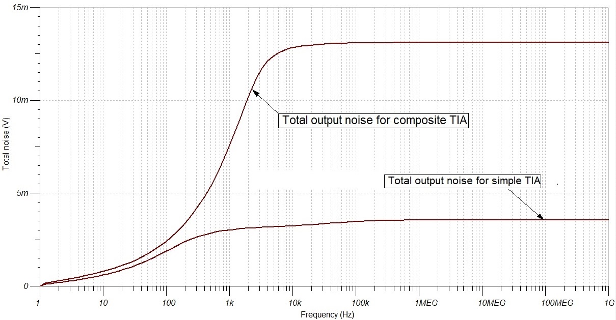 Figure 4-6 Effect of 1-GΩ TIA Implementation on the Total Output Noise