SBOA615 November 2024 INA180 , INA180-Q1 , INA181 , INA181-Q1 , INA183 , INA185 , INA185-Q1 , INA186 , INA186-Q1 , INA190 , INA190-EP , INA190-Q1 , INA191 , INA199 , INA199-Q1 , INA209 , INA210 , INA210-Q1 , INA211 , INA211-Q1 , INA212 , INA212-Q1 , INA213 , INA213-Q1 , INA214 , INA214-Q1 , INA215 , INA215-Q1 , INA216 , INA2180 , INA2180-Q1 , INA2181 , INA2181-Q1 , INA219 , INA2191 , INA220 , INA220-Q1 , INA223 , INA225 , INA225-Q1 , INA226 , INA226-Q1 , INA228 , INA228-Q1 , INA229 , INA229-Q1 , INA2290 , INA230 , INA231 , INA232 , INA233 , INA234 , INA236 , INA237 , INA237-Q1 , INA238 , INA238-Q1 , INA239 , INA239-Q1 , INA240 , INA240-Q1 , INA241A , INA241A-Q1 , INA241B , INA241B-Q1 , INA250 , INA250-Q1 , INA253 , INA253-Q1 , INA254 , INA260 , INA280 , INA280-Q1 , INA281 , INA281-Q1 , INA290 , INA290-Q1 , INA293 , INA293-Q1 , INA296A , INA296A-Q1 , INA296B , INA296B-Q1 , INA300 , INA300-Q1 , INA301 , INA301-Q1 , INA302 , INA302-Q1 , INA303 , INA303-Q1 , INA310A , INA310A-Q1 , INA310B , INA310B-Q1 , INA3221 , INA3221-Q1 , INA381 , INA381-Q1 , INA4180 , INA4180-Q1 , INA4181 , INA4181-Q1 , INA4230 , INA4235 , INA4290 , INA700 , INA740A , INA740B , INA745A , INA745B , INA780A , INA780B , INA790B , INA791B , LMP8278Q-Q1 , LMP8601 , LMP8601-Q1 , LMP8602 , LMP8602-Q1 , LMP8603 , LMP8603-Q1 , LMP8640 , LMP8640-Q1 , LMP8640HV
- 1
- Abstract
- Trademarks
- 1Introduction
- 2What is ESD, EOS, and Latch Up?
- 3Risky Applications for Current Sense Amplifiers
- 4Summary
- 5References
3.3.1.3 Proper Input Filtering Layout Techniques for Noise Reduction
- Input traces are considered a differential net and kept as close together as possible.
- Input traces go through input common-mode capacitors (CCM) and differential capacitor (CDIFF) pads.
- Input resistors (RFILTER) are kept under 10Ω (or 1kΩ for capacitive-coupled input CSAs such as the INA186, INA190, or INAx191). If higher input resistors are needed, then refer to this Input Resistance Error for Current Sense Amplifiers, user's guide on calculating error increase.
- CCM and CDIFF are placed close to the CSA input pins.
- CCM has a low-impedance, direct path to CSA ground pin.
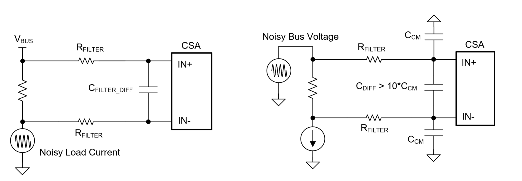
- CDIFF is greater than 10 times the CCM value. The reason for this is to negate effects of mismatches in CCM and resulting dynamic offsets, thus keeping the sense voltage stable during sudden VCM changes.
- If using a capacitive-coupled CSA, the requirement is usually to add a CDIFF of > 1nF to keep input front-end capacitors stable for loads with periodic current transients or when input resistors are high or input traces are long creating high input inductance. See data sheet and this Input Resistance Error for Current Sense Amplifiers, user's guide for more information.
Figure 3-5 shows the general schematic for filtering input noise on CSAs.
 Figure 3-5 Input Filtering for EMI Induced Noise