SBOK078 October 2023 SN54SC4T08-SEP
PRODUCTION DATA
5.1 SEL Results
During SEL characterization, the device was heated using forced hot air, maintaining IC temperature at 125°C. A FLIR (FLIR ONE Pro LT) thermal camera was used to validate die temperature to ensure the device was being accurately heated (see Figure 3-5). The species used for SEL testing was a Xenon (129Xe) ion at a linac energy of 25 MeV / µ with an angle-of-incidence of 0° for an LETEFF of 43 MeV-cm2 / mg. A fluence of approximately 1 × 10⁷ ions / cm2 were used for the runs.
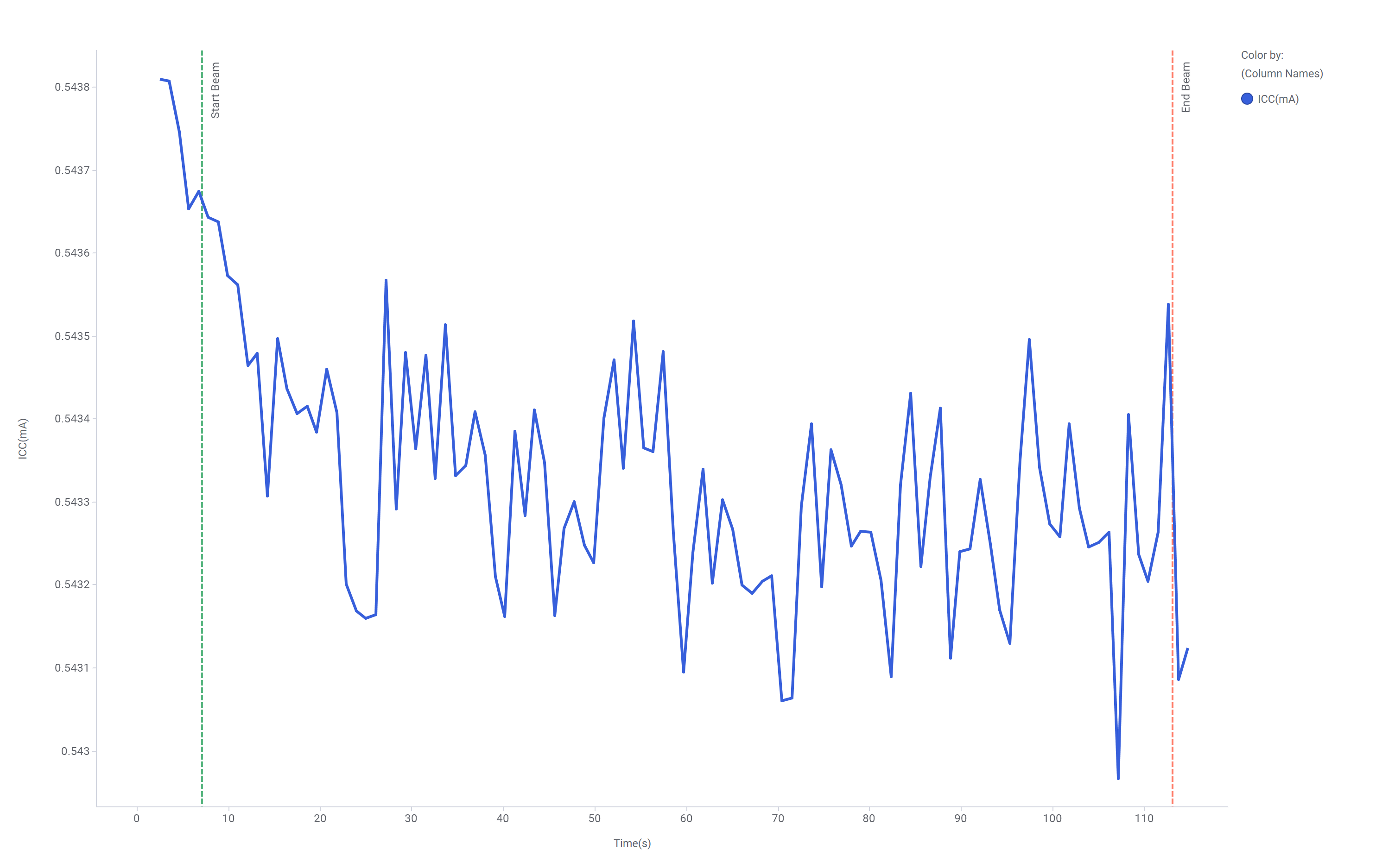
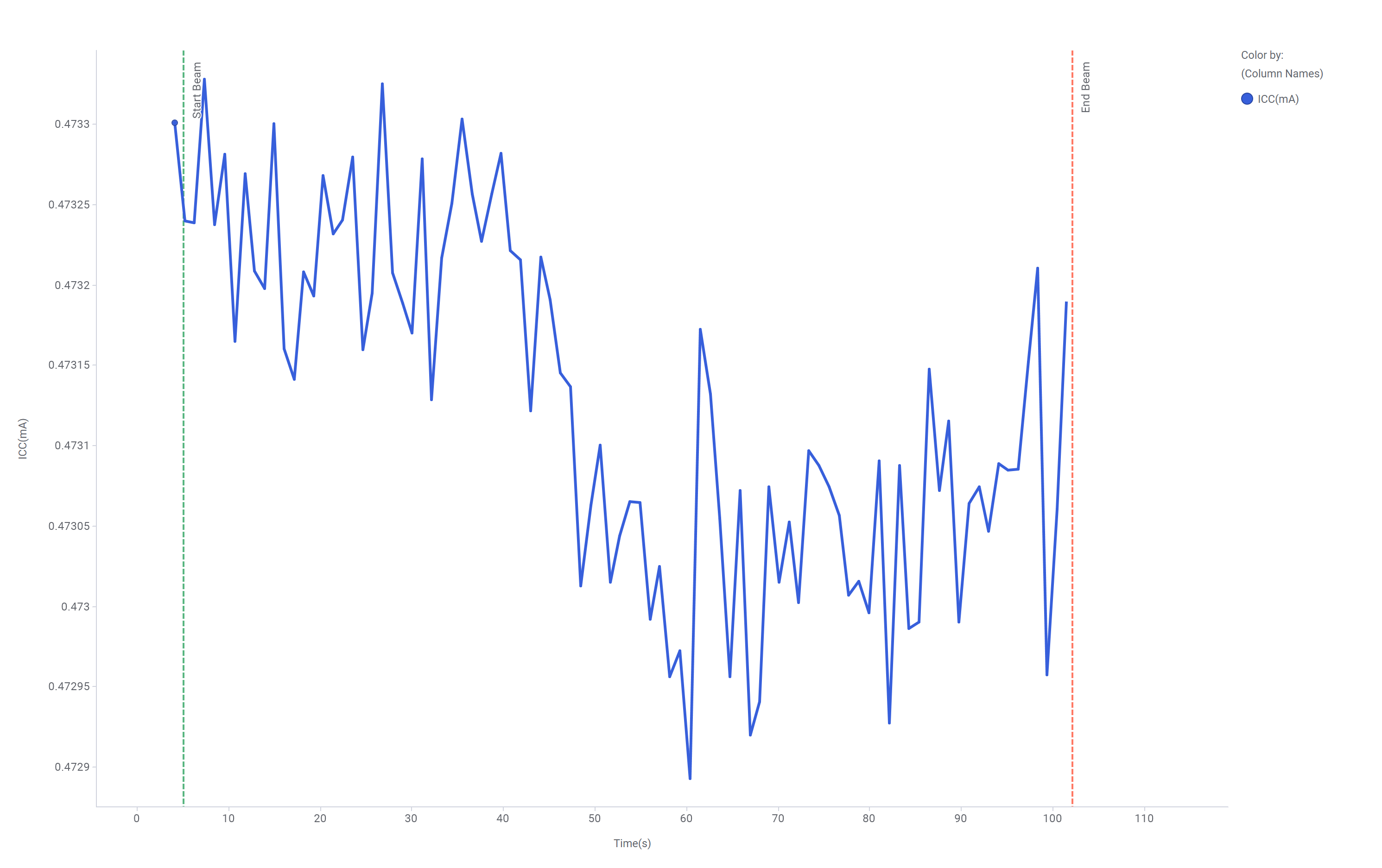
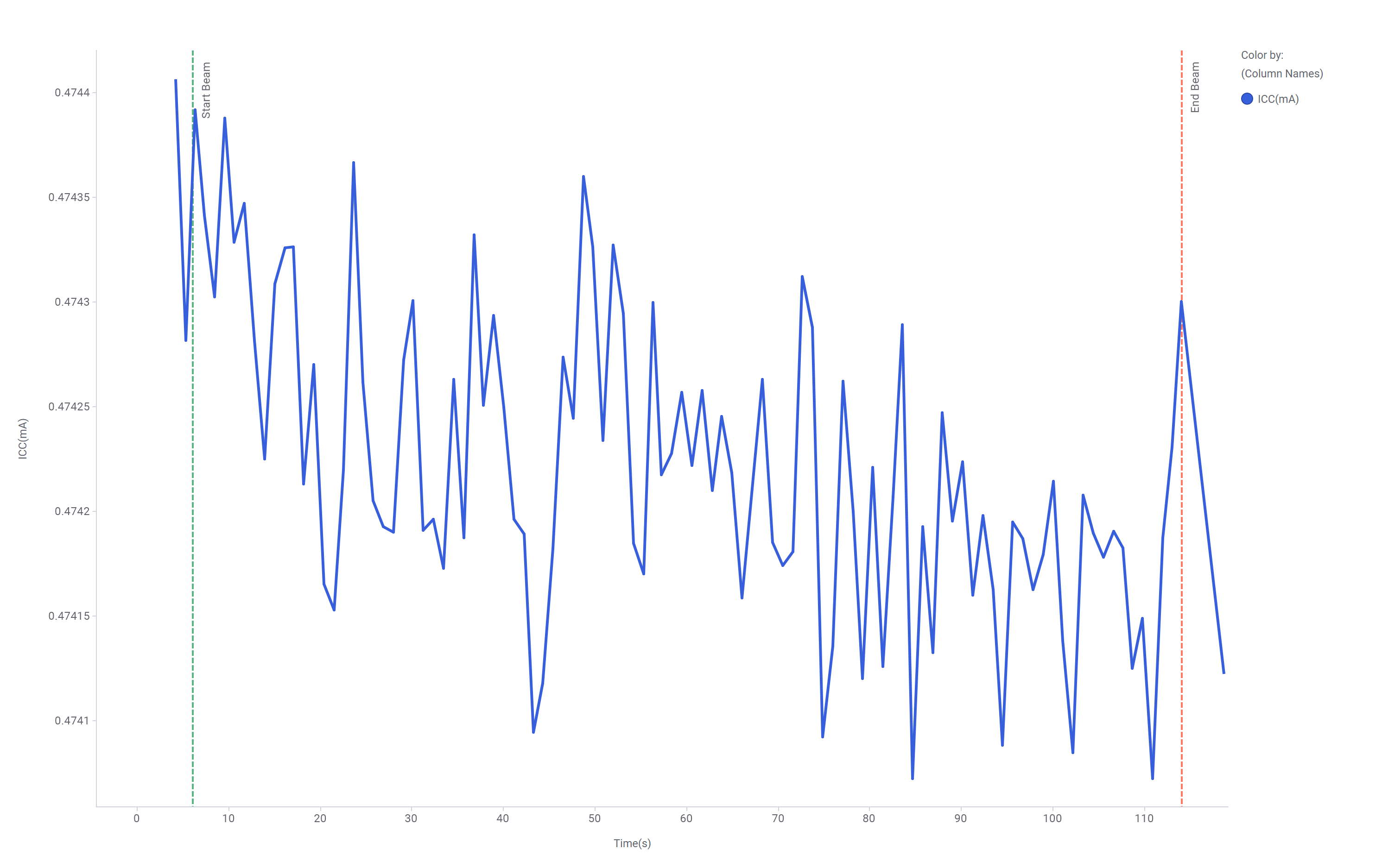
The three devices were powered up and exposed to the heavy-ions using the maximum recommended supply voltage of 5.5-V using a National Instruments PXI Chassis PXIe-1085 and a 5-V, 1 MHz square wave input using a Tektronix AFG3102 function generator. The run duration to achieve this fluence was approximately two minutes. As listed in Table 5-1, no SEL events were observed during the nine runs, which indicates that the SN54SC4T08-SEP is SEL-free. Figure 5-1, Figure 5-2, and Figure 5-3 show the plot of current versus time for run numbers 1, 4, and 7, respectively.
| Run Number | Unit Number | Ion | Distance (mm) | Angle | Temperature (°C) | LETEFF (MeV × cm2 / mg) | Flux (ions × cm2 / mg) | Fluence ( ions) | Did an SEL event occur? |
|---|---|---|---|---|---|---|---|---|---|
| 1 | 1 | Xe | 70 | 0° | 126 | 43 | 1.0E+05 | 1.0E+07 | No |
| 2 | 1 | Xe | 70 | 0° | 126 | 43 | 1.0E+05 | 1.0E+07 | No |
| 3 | 1 | Xe | 70 | 0° | 126 | 43 | 1.0E+05 | 1.0E+07 | No |
| 4 | 2 | Xe | 70 | 0° | 125 | 43 | 1.0E+05 | 1.0E+07 | No |
| 5 | 2 | Xe | 70 | 0° | 125 | 43 | 1.0E+05 | 1.0E+07 | No |
| 6 | 2 | Xe | 70 | 0° | 125 | 43 | 1.0E+05 | 1.0E+07 | No |
| 7 | 3 | Xe | 70 | 0° | 125 | 43 | 1.0E+05 | 1.0E+07 | No |
| 8 | 3 | Xe | 70 | 0° | 125 | 43 | 1.0E+05 | 1.0E+07 | No |
| 9 | 3 | Xe | 70 | 0° | 125 | 43 | 1.0E+05 | 1.0E+07 | No |
 Figure 5-1 Current versus Time for Run 1
of the SN54SC4T08-SEP at T = 125°C
 Figure 5-2 Current versus Time for Run 4
of the SN54SC4T08-SEP at T = 125°C
 Figure 5-3 Current versus Time for Run 7
of the SN54SC4T08-SEP at T = 125°C
Figure 5-3 Current versus Time for Run 7
of the SN54SC4T08-SEP at T = 125°CUsing the MFTF method described in Single-Event Effects (SEE) Confidence Internal Calculations application report, the upper-bound cross section (using a 95% confidence level) is calculated as: