SBOU122B September 2013 – August 2016 INA118 , INA121 , INA122 , INA126 , INA129 , INA141 , INA155 , INA156 , INA188 , INA317 , INA818 , INA821 , INA828
2 PCB Layout
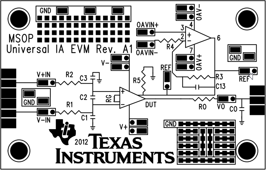
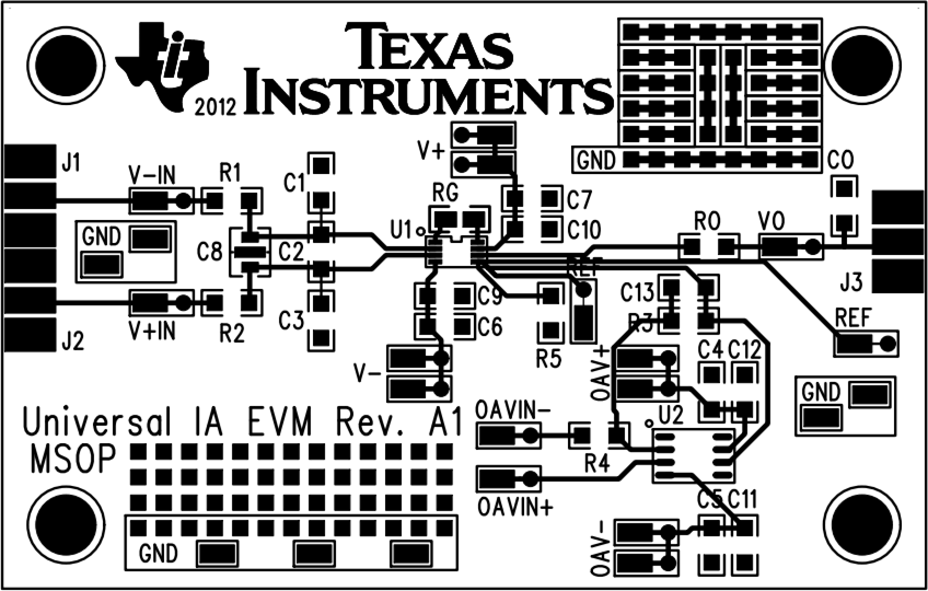
The schematic and component sides of the VSSOP-8 EVM are shown in Figure 2 and Figure 3, respectively.
NOTE
Board layouts are not to scale. These figures are intended to show how the board is laid out; they are not intended to be used for manufacturing PCBs.
 Figure 2. Universal IA EVM Schematic Side (VSSOP-8)
  Figure 3. Universal IA EVM Component Side (VSSOP-8)
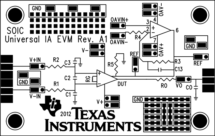
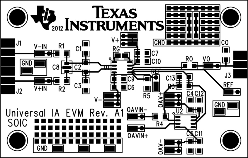
 The schematic and component sides of the SOIC-8 EVM are shown in Figure 4 and Figure 5, respectively.
 Figure 4. Universal IA EVM Schematic Side (SOIC-8)
  Figure 5. Universal IA EVM Component Side (SOIC-8)