SBOU162A March 2017 – May 2017
-
DIYAMP-SOIC-EVM
- Trademarks
- 1 Introduction
- 2 Hardware Setup
- 3
Schematic and PCB Layout
- 3.1 Schematic PCB Drawing
- 3.2 Single-Supply, Multiple Feedback Filter
- 3.3 Single-Supply, Sallen-Key Filter
- 3.4 Single-Supply, Non-Inverting Amplifier
- 3.5 Single-Supply, Inverting Amplifier
- 3.6 Difference Amplifier
- 3.7 Dual-Supply, Multiple Feedback Filter
- 3.8 Dual-Supply, Sallen-Key Filter
- 3.9 Inverting Comparator
- 3.10 Non-Inverting Comparator
- 3.11 Riso With Dual Feedback
- 3.12 Dual-Supply, Non-Inverting Amplifier
- 3.13 Dual-Supply, Inverting Amplifier
- 4 Connections
- 5 Bill of Materials and Reference
- Revision History
2.2 EVM Assembly Instructions
This section has step-by-step instructions on how to assemble a circuit configuration from the EVM.
- Choose the desired circuit configuration. See Section 2.1 for the location of each circuit configuration.
- Gently flex the PCB panel at the score lines to separate the desired circuit configuration from the EVM.
- Solder device and surface mount passive components to the separated PCB.
- Use long-nose pliers to break header strips, provided in the EVM kit, into 4-position lengths.
- Insert header strips into a spare DIP socket as shown in Figure 5.
- Position separated PCB over pins and solder the connections. Carefully remove from the DIP socket.
- Attach SMA connectors, test points, or wires to the input and output of the separated PCB.
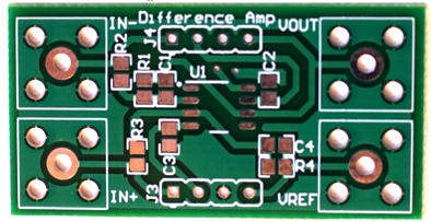 Figure 2. Detach Desired Circuit Configuration
 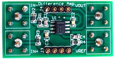 Figure 3. Detach Configuration With Attached IC and Passive Components
 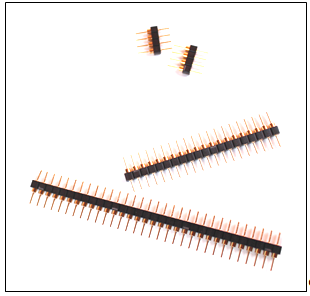 Figure 4. Terminal Strip (TS-132-G-AA) Broken Into 4-Pin Lengths
 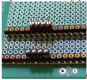 Figure 5. 4-Pin Length Terminal Strips Inserted in DIP Socket
 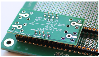 Figure 6. Detached Board Configuration Position Over Terminal Pins
 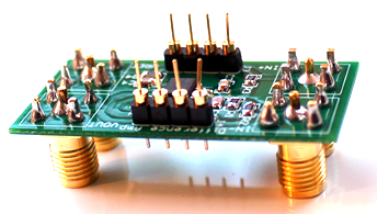 Figure 7. Fully-Assembled Circuit Configuration From DIYAMP-SOIC-EVM