SBOU192 July 2017
-
DIYAMP-SC70-EVM
- Trademarks
- 1 Introduction
- 2 Hardware Setup
- 3
Schematic and PCB Layout
- 3.1 Schematic PCB Drawing
- 3.2 Single-Supply, Multiple Feedback Filter
- 3.3 Single-Supply, Sallen-Key Filter
- 3.4 Single-Supply, Non-Inverting Amplifier
- 3.5 Single-Supply, Inverting Amplifier
- 3.6 Difference Amplifier
- 3.7 Dual-Supply, Multiple Feedback Filter
- 3.8 Dual-Supply, Sallen-Key Filter
- 3.9 Inverting Comparator
- 3.10 Non-Inverting Comparator
- 3.11 Riso With Dual Feedback
- 3.12 Dual-Supply, Non-Inverting Amplifier
- 3.13 Dual-Supply, Inverting Amplifier
- 4 Connections
- 5 Bill of Materials and Reference
4.2 Power
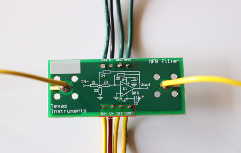
This EVM features both dual- and single-supply, op-amp configurations. Power can only be applied using the header pins located at the top and bottom of the PCB. The positive supply is labeled V+, the negative supply is labeled V–, and ground is labeled GND. As an alternative, wire can be used in place of the included terminals strips to power the board directly. Figure 51 shows an all-wire assembly for a multiple feedback filter configuration.
 Figure 51. Wire Alternative for Terminal Area