SBOU192 July 2017
-
DIYAMP-SC70-EVM
- Trademarks
- 1 Introduction
- 2 Hardware Setup
- 3
Schematic and PCB Layout
- 3.1 Schematic PCB Drawing
- 3.2 Single-Supply, Multiple Feedback Filter
- 3.3 Single-Supply, Sallen-Key Filter
- 3.4 Single-Supply, Non-Inverting Amplifier
- 3.5 Single-Supply, Inverting Amplifier
- 3.6 Difference Amplifier
- 3.7 Dual-Supply, Multiple Feedback Filter
- 3.8 Dual-Supply, Sallen-Key Filter
- 3.9 Inverting Comparator
- 3.10 Non-Inverting Comparator
- 3.11 Riso With Dual Feedback
- 3.12 Dual-Supply, Non-Inverting Amplifier
- 3.13 Dual-Supply, Inverting Amplifier
- 4 Connections
- 5 Bill of Materials and Reference
3.3 Single-Supply, Sallen-Key Filter
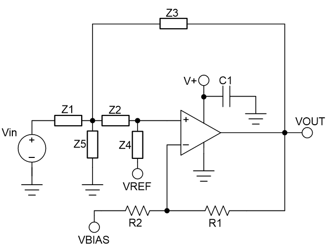
Figure 12 shows the schematic for the single-supply, Sallen-Key filter circuit configuration.
 Figure 12. Single-Supply, Sallen-Key Filter Schematic
 Sallen-Key is one of the most commonly applied active filter topologies. The Sallen-Key is a non-inverting, voltage-controlled, voltage-source (VCVS) able to attain larger Qs with a stable response than other filter topologies. Because Sallen-Key is non-inverting, it might be preferable over the MFB topology.
The single-supply, Sallen-Key filter can be configured as a low-pass filter, high-pass filter, or band-pass filter based on the component selection of Z1 through Z5. Table 4 displays the type of passive component that should be chosen for Z1 through Z5 for each filter configuration.
Table 4. Sallen-Key Filter Component Type Selection
| Pass-Band
Filter Type |
Type of Component (Z1) | Type of Component (Z2) | Type of Component (Z3) | Type of Component (Z4) | Type of Component (Z5) |
|---|---|---|---|---|---|
| Low Pass | R1 | R2 | C3 | C4 | Not populated |
| High Pass | C1 | C2 | R3 | R4 | Not populated |
| Band Pass | R1 | C2 | R3 | R4 | C5 |
For additional guidance in designing a filter, download the FilterPro active filter design software.
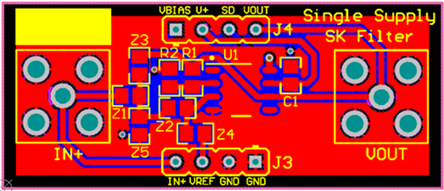
The PCB layout of the top layer of the single-supply, Sallen-Key filter circuit configuration is displayed in Figure 13.
 Figure 13. Single-Supply, Sallen-Key Filter Top Layer
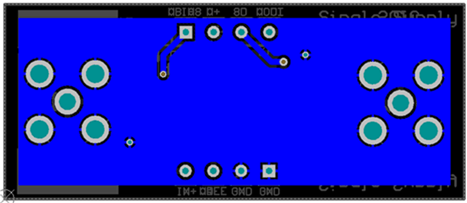
 The PCB layout of the bottom layer of the single-supply, Sallen-Key filter configuration is displayed in Figure 14.
 Figure 14. Single-Supply, Sallen-Key Filter Bottom Layer