SBVU072 October 2021 TPS7A21
Abstract
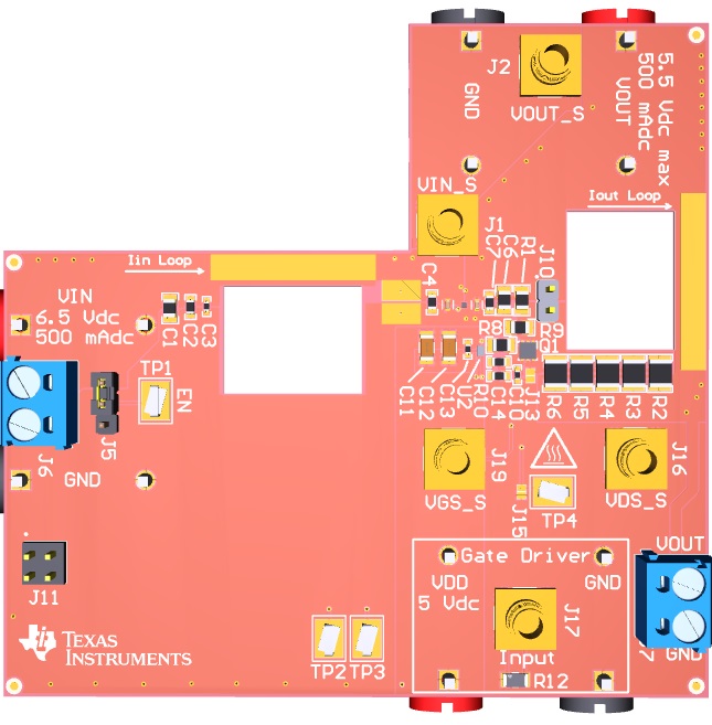
 Figure 1-1 TPS7A21EVM-059 Evaluation
Module
Figure 1-1 TPS7A21EVM-059 Evaluation
ModuleThis user's guide describes the operational use of the TPS7A21EVM-059 evaluation module (EVM) as a reference design for engineering demonstration and evaluation of the TPS7A21 low-dropout linear regulator (LDO). Included in this user's guide are setup and operating instructions, thermal and layout guidelines, a printed-circuit board (PCB) layout, a schematic diagram, and a bill of materials (BOM).
Throughout this document, the terms evaluation board, evaluation module, and EVM are synonymous with the TPS7A21EVM-059.