SFFS222 October 2023 TMS320F2800153-Q1 , TMS320F2800154-Q1 , TMS320F2800155-Q1 , TMS320F2800156-Q1 , TMS320F2800157 , TMS320F2800157-Q1
- 1
- Trademarks
- 1Introduction
- 2TMS320F280015x Hardware Component Functional Safety Capability
- 3TI Development Process for Management of Systematic Faults
- 4TMS320F280015x Component Overview
- 5Description of Safety Elements
-
6Management of Random Faults
- 6.1 Fault Reporting
- 6.2 Suggestions for Improving Freedom From Interference
- 6.3 Suggestions for Addressing Common Cause Failures
- 6.4
Description of Functional Safety Mechanisms
- 6.4.1
TMS320F280015x MCU Infrastructure Components
- 6.4.1.1 Clock Integrity Check Using DCC
- 6.4.1.2 Clock Integrity Check Using CPU Timer
- 6.4.1.3 Clock Integrity Check Using HRPWM
- 6.4.1.4 EALLOW Protection for Critical Registers
- 6.4.1.5 External Monitoring of Clock via XCLKOUT
- 6.4.1.6 External Monitoring of Warm Reset (XRSn)
- 6.4.1.7 External Voltage Supervisor
- 6.4.1.8 External Watchdog
- 6.4.1.9 Glitch Filtering on Reset Pins
- 6.4.1.10 Hardware Disable of JTAG Port
- 6.4.1.11 Lockout of JTAG Access Using OTP
- 6.4.1.12 Internal Watchdog (WD)
- 6.4.1.13 Lock Mechanism for Control Registers
- 6.4.1.14 Missing Clock Detect (MCD)
- 6.4.1.15 NMIWD Reset Functionality
- 6.4.1.16 NMIWD Shadow Registers
- 6.4.1.17 Multi-Bit Enable Keys for Control Registers
- 6.4.1.18 Online Monitoring of Temperature
- 6.4.1.19 Periodic Software Read Back of Static Configuration Registers
- 6.4.1.20 Peripheral Clock Gating (PCLKCR)
- 6.4.1.21 Peripheral Soft Reset (SOFTPRES)
- 6.4.1.22 Software Test of Reset - Type 1
- 6.4.1.23 PLL Lock Profiling Using On-Chip Timer
- 6.4.1.24 Reset Cause Information
- 6.4.1.25 Software Read Back of Written Configuration
- 6.4.1.26 Software Test of ERRORSTS Functionality
- 6.4.1.27 Software Test of Missing Clock Detect Functionality
- 6.4.1.28 Software Test of Watchdog (WD) Operation
- 6.4.1.29 Dual-Clock Comparator (DCC) - Type 2
- 6.4.1.30 PLL Lock Indication
- 6.4.1.31 Software Test of DCC Functionality Including Error Tests
- 6.4.1.32 Software Test of PLL Functionality Including Error Tests
- 6.4.1.33 Interleaving of FSM States
- 6.4.1.34 Brownout Reset (BOR)
- 6.4.2
Processing Elements
- 6.4.2.1 CPU Handling of Illegal Operation, Illegal Results and Instruction Trapping
- 6.4.2.2 Software Test of CPU
- 6.4.2.3 Stack Overflow Detection
- 6.4.2.4 VCRC Check of Static Memory Contents
- 6.4.2.5 VCRC Auto Coverage
- 6.4.2.6 Hardware Redundancy Using Lockstep Compare Module (LCM)
- 6.4.2.7 Self-test Logic for LCM
- 6.4.2.8 LCM Compare Error Forcing Mode
- 6.4.2.9 LCM MMR Parity
- 6.4.2.10 Test of LCM MMR Parity
- 6.4.2.11 Lockstep Self-test Mux Select Logic Fault Detection
- 6.4.2.12 Redundancy in LCM Comparator
- 6.4.3
Memory (Flash, SRAM and ROM)
- 6.4.3.1 Bit Multiplexing in Flash Memory Array
- 6.4.3.2 Bit Multiplexing in SRAM Memory Array
- 6.4.3.3 Data Scrubbing to Detect/Correct Memory Errors
- 6.4.3.4 Flash ECC
- 6.4.3.5 Flash Program Verify and Erase Verify Check
- 6.4.3.6 Flash Program/Erase Protection
- 6.4.3.7 Flash Wrapper Error and Status Reporting
- 6.4.3.8 Prevent 0 to 1 Transition Using Program Command
- 6.4.3.9 On-demand Software Program Verify and Blank Check
- 6.4.3.10 CMDWEPROT* and Program Command Data Buffer Registers Self-Clear After Command Execution
- 6.4.3.11 ECC Generation and Checker Logic is Separate in Hardware
- 6.4.3.12 Auto ECC Generation Override
- 6.4.3.13 Software Test of ECC Logic
- 6.4.3.14 Software Test of Flash Prefetch, Data Cache and Wait-States
- 6.4.3.15 Access Protection Mechanism for Memories
- 6.4.3.16 SRAM ECC
- 6.4.3.17 SRAM Parity
- 6.4.3.18 Software Test of Parity Logic
- 6.4.3.19 Software Test of SRAM
- 6.4.3.20 Memory Power-On Self-Test (MPOST)
- 6.4.3.21 ROM Parity
- 6.4.4
On-Chip Communication Including Bus-Arbitration
- 6.4.4.1 1oo2 Software Voting Using Secondary Free Running Counter
- 6.4.4.2 Maintaining Interrupt Handler for Unused Interrupts
- 6.4.4.3 Power-Up Pre-Operational Security Checks
- 6.4.4.4 Majority Voting and Error Detection of Link Pointer
- 6.4.4.5 Software Check of X-BAR Flag
- 6.4.4.6 Software Test of ePIE Operation Including Error Tests
- 6.4.5
Digital I/O
- 6.4.5.1 eCAP Application Level Safety Mechanism
- 6.4.5.2 ePWM Application Level Safety Mechanism
- 6.4.5.3 ePWM Fault Detection Using X-BAR
- 6.4.5.4 ePWM Synchronization Check
- 6.4.5.5 eQEP Application Level Safety Mechanism
- 6.4.5.6 eQEP Quadrature Watchdog
- 6.4.5.7 eQEP Software Test of Quadrature Watchdog Functionality
- 6.4.5.8 Hardware Redundancy
- 6.4.5.9 HRPWM Built-In Self-Check and Diagnostic Capabilities
- 6.4.5.10 Information Redundancy Techniques
- 6.4.5.11 Monitoring of ePWM by eCAP
- 6.4.5.12 Monitoring of ePWM by ADC
- 6.4.5.13 Online Monitoring of Periodic Interrupts and Events
- 6.4.5.14 Software Test of Function Including Error Tests
- 6.4.5.15 QMA Error Detection Logic
- 6.4.6
Analog I/O
- 6.4.6.1 ADC Information Redundancy Techniques
- 6.4.6.2 ADC Input Signal Integrity Check
- 6.4.6.3 ADC Signal Quality Check by Varying Acquisition Window
- 6.4.6.4 CMPSS Ramp Generator Functionality Check
- 6.4.6.5 DAC to ADC Loopback Check
- 6.4.6.6 Opens/Shorts Detection Circuit for ADC
- 6.4.6.7 Disabling Unused Sources of SOC Inputs to ADC
- 6.4.7
Data Transmission
- 6.4.7.1 Information Redundancy Techniques Including End-to-End Safing
- 6.4.7.2 Bit Error Detection
- 6.4.7.3 CRC in Message
- 6.4.7.4 DCAN Acknowledge Error Detection
- 6.4.7.5 DCAN Form Error Detection
- 6.4.7.6 DCAN Stuff Error Detection
- 6.4.7.7 PWM Trip by MCAN
- 6.4.7.8 MCAN Acknowledge Error Detection
- 6.4.7.9 MCAN Form Error Detection
- 6.4.7.10 MCAN Stuff Error Detection
- 6.4.7.11 Timeout on FIFO Activity
- 6.4.7.12 Timestamp Consistency Checks
- 6.4.7.13 Tx-Event Checks
- 6.4.7.14 Interrupt on Message RAM Access Failure
- 6.4.7.15 Software Test of Function Including Error Tests Using EPG
- 6.4.7.16 I2C Access Latency Profiling Using On-Chip Timer
- 6.4.7.17 I2C Data Acknowledge Check
- 6.4.7.18 Parity in Message
- 6.4.7.19 SCI Break Error Detection
- 6.4.7.20 Frame Error Detection
- 6.4.7.21 Overrun Error Detection
- 6.4.7.22 Software Test of Function Using I/O Loopback
- 6.4.7.23 SPI Data Overrun Detection
- 6.4.7.24 Transmission Redundancy
- 6.4.7.25 LIN Physical Bus Error Detection
- 6.4.7.26 LIN No-Response Error Detection
- 6.4.7.27 LIN Checksum Error Detection
- 6.4.7.28 Data Parity Error Detection
- 6.4.7.29 LIN ID Parity Error Detection
- 6.4.7.30 PMBus Protocol CRC in Message
- 6.4.7.31 Clock Timeout
- 6.4.7.32 Communication Access Latency Profiling Using On-Chip Timer
- 6.4.1
TMS320F280015x MCU Infrastructure Components
- 7References
- A Summary of Safety Features and Diagnostics
- B Distributed Developments
4.2.1 VDA E-GAS Monitoring Concept With TMS320F280015x MCU
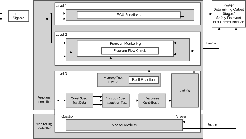
The standardized E-GAS monitoring concept [6] for engine management systems generated by the German VDA working group “E-Gas-Arbeitskreis” is an example of a well-trusted safety-architecture that may be used for applications other than engine management systems provided it fits the purpose of the new application in terms of diagnosis feasibility, environment constraints, time constraints, robustness, and so forth [7]. For more information, see Figure 4-3 .
 Figure 4-3 E-GAS System Overview From
Standard
Figure 4-3 E-GAS System Overview From
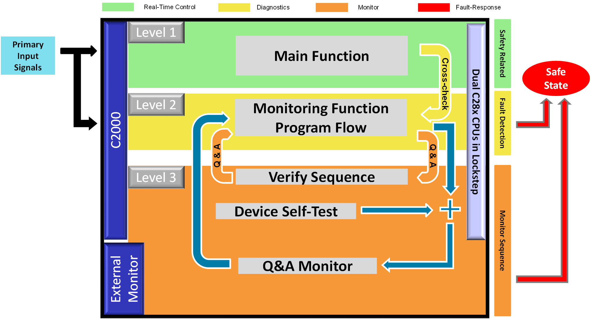
StandardThe MCU device family supports heterogeneous asymmetric architecture and their functional safety features lend themselves to an E-GAS concept implementation at system level as indicated in Figure 4-4. In the first level (Level 1), the functions required for the system mission are computed. Second level (Level 2) checks the correct formation in first level based on selected set of parameters. Third level (Level 3) implements an additional external monitoring element, for the correct carrying out of the mission in the first level and/or monitoring in the second level. The exact functional safety implementation and the modules used for realizing Level 1 and Level 2 and the external monitoring device for realizing Level 3 are left to the system designer.
 Figure 4-4 VDA E-Gas Monitoring Concept
Applied to F280015x MCU
Figure 4-4 VDA E-Gas Monitoring Concept
Applied to F280015x MCUDue to the inherent versatility of the device architecture, several software voting based functional safety configurations are possible. While implementing these configurations, system integrator needs to consider the potential common mode failures and address them in an appropriate manner. This may suitably be modified to adapt to TMS320F280015x requirements based on the availability of processing units. (As stated earlier, the device claims no hardware fault tolerance, (for example, no claims of HFT > 0), as defined in IEC 61508:2010).
The major safety features of TMS320F280015x are shown in Figure 4-5.
 Figure 4-5 TMS320F280015x MCU With Safety Features