SFFS422 May 2022
- Trademarks
- 2
- 1Scope
- 2Related Documents
- 3Related Standards and Acronyms
-
4Concept Overview
- 4.1 System Block Diagram
- 4.2 System Specifications
- 4.3 Conditions of use: Assumptions
- 4.4 Safe Torque Off Implementation
- 4.5 Safe State
- 5Concept FMEA
- 6References
4.4.6 STO_FB Subsystem
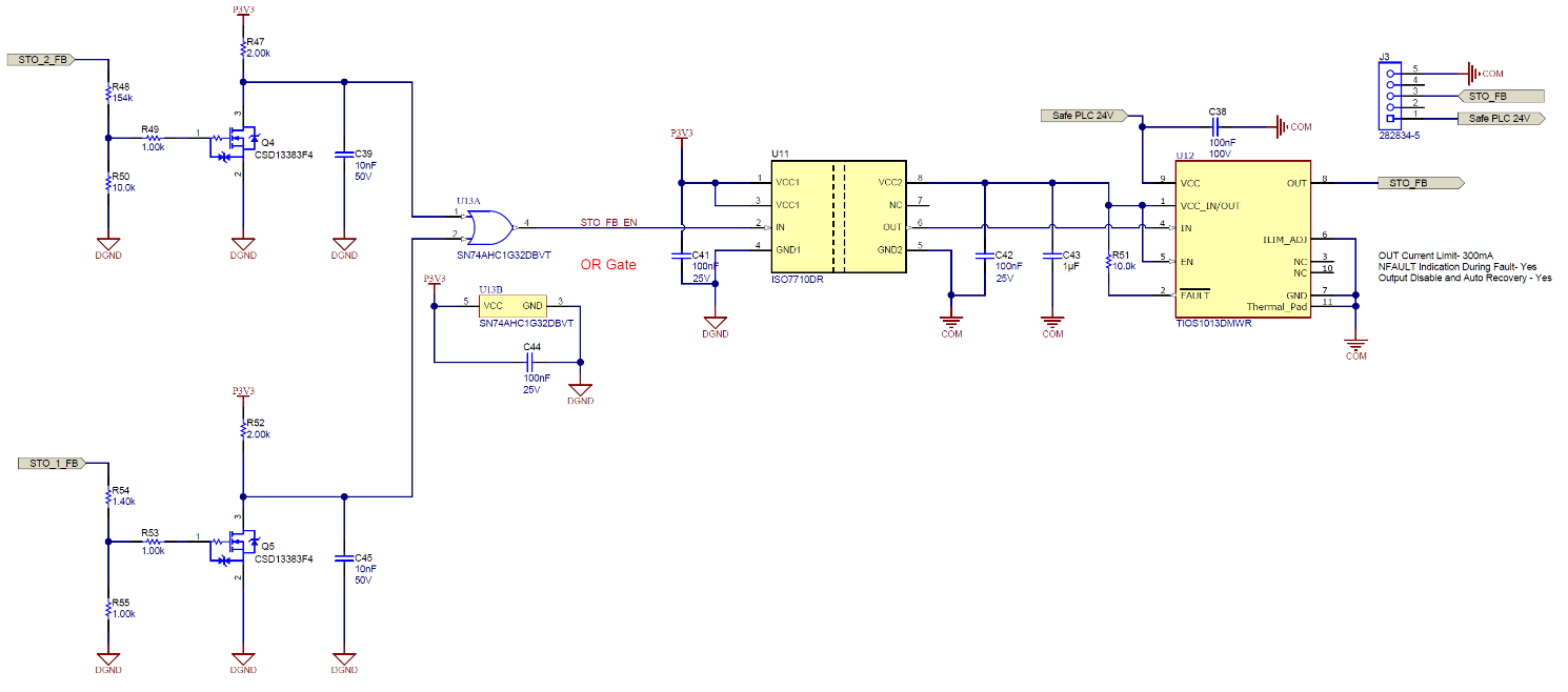
The STO_FB signal is an active low signal and indicates the drive state. A high signal (logic level 1) indicates normal drive operation, while a low signal (logic state 0) indicates the drive is in the safe state. The schematic is shown in Figure 4-7. The output signals STO_1_FB and STO_2_FB of the corresponding STO_1 and STO_2 safe subsystems are logically combined to a single active low feedback signal STO_FB through an isolated 24-V digital output. The corresponding logic states are shown in Table 4-4.
 Figure 4-7 STO_FB Feedback Monitor
Subsystem
Figure 4-7 STO_FB Feedback Monitor
Subsystem| Input 1: STO_1 | Input 2: STO_2 |
Output_1: STO_1_FB (Monitor_1) |
Output_2: STO_2_FB (Monitor_2) |
Drive State | STO_FB | Comment |
|---|---|---|---|---|---|---|
| 1 | 1 | 1 | 1 | Normal operation | 1 | |
| 0 | 0 | 0 | 0 | Safe state (off) | 0 | |
| 1 | 1 | 0 |
1 (stuck high fault) |
Safe state (off) | 0 | (1) The MCU has detected a single dangerous fault (stuck high) in subsystem STO_2 and has triggered the safe state through STO_1 subsystem. |
| 1 | 1 |
1 (stuck high fault) |
0 | Safe state (off) | 0 | (2) The MCU has detected a single dangerous fault (stuck high) in subsystem STO_1 and has triggered the safe state through STO_2 subsystem. |
| 0 | 0 | 0 |
1 (stuck high fault) |
Safe state (off) | 0 | Single detected fault could be detected earlier already, see (1) in above row. |
| 0 | 0 |
1 (stuck high fault) |
0 | Safe state (off) | 0 | Single detected fault could be detected earlier already, see (2) in above row. |
| 0 | 0 |
1 (stuck high fault) |
1 (stuck high fault) |
Normal operation | 1 | Dangerous state, due to two dangerous faults, one in each safe subsystem STO_1 and STO_2. |
The STO_FB signal can be active low (logic state 0), while both STO_1 and STO_2 are inactive high (logic state 1). This state occurs when the diagnostics MCU (SIL 1) detects a single dangerous fault in one of the STO_1 or STO_2 subsystems. If a short or stuck high was found, the MCU puts the 3-phase IGBT inverter into a safe state by driving both diagnostic pulses MCU_Diag_Cntrl_Out1 and MCU_Diag_Cntrl_Out2 continuously low. This state can be used for example by an external safety PLC to recognize a single fault in either STO_1 or STO_2 systems and take appropriate actions. The safety PLC and related action are out of scope for this concept analysis.