SLAA457B September 2013 – October 2018 MSP430F5500 , MSP430F5501 , MSP430F5502 , MSP430F5503 , MSP430F5504 , MSP430F5505 , MSP430F5506 , MSP430F5507 , MSP430F5508 , MSP430F5509 , MSP430F5510 , MSP430F5513 , MSP430F5514 , MSP430F5515 , MSP430F5517 , MSP430F5519 , MSP430F5521 , MSP430F5522 , MSP430F5524 , MSP430F5525 , MSP430F5526 , MSP430F5527 , MSP430F5528 , MSP430F5529 , MSP430F5630 , MSP430F5631 , MSP430F5632 , MSP430F5633 , MSP430F5634 , MSP430F5635 , MSP430F5636 , MSP430F5637 , MSP430F5638 , MSP430F5658 , MSP430F5659 , MSP430F6630 , MSP430F6631 , MSP430F6632 , MSP430F6633 , MSP430F6634 , MSP430F6635 , MSP430F6636 , MSP430F6637 , MSP430F6638 , MSP430F6658 , MSP430F6659 , MSP430FG6425 , MSP430FG6426 , MSP430FG6625 , MSP430FG6626
6.4 FET Target Boards
For every MSP430 device, TI provides simple evaluation boards called "FET target boards".
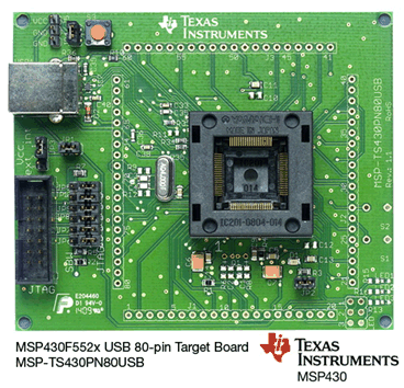
 Figure 14. MSP-TS430PN80USB FET Target Board for F552x
 Table 6. FET Target Boards for USB-Equipped MSP430 Derivatives
| USB-Equipped MSP430 Family | FET Target Board |
|---|---|
| MSP430F550x, MSP430F5510 | MSP-TS430RGC64USB |
| MSP430F552x | MSP-TS430RGC64USB |
| MSP-TS430PN80USB | |
| MSP430F563x, MSP430F663x | MSP-TS430PZ100USB |
| MSP430F565x, MSP430F665x | MSP-TS430PZ100USB |
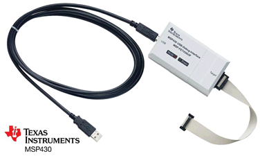
FET target boards are available for every MSP430 derivative, not just the MSP430F5529. However, they do not have an on-board emulator, as the F5529 LaunchPad development kit and F5529 Experimenter's Board do; and so they require a FET Tool for emulation.
 Figure 15. FET Tool (MSP-FET430UIF) Emulator
 The FET Tool interfaces to hardware using the 14-pin JTAG header shown at left in Figure 14.
FET target boards contain:
- A socket for the MSP430 device
- The minimum circuitry required for basic operation
- Two pushbuttons and an LED
- All of the MSP430 pins brought out to headers
- A USB connector
The FET target boards relevant to USB-equipped derivatives are shown at http://www.ti.com/msp430usb.