SLAA654A November 2014 – July 2015 CC430F6147 , MSP430F412 , MSP430F413 , MSP430F4132 , MSP430F415 , MSP430F4152 , MSP430F417 , MSP430F423A , MSP430F4250 , MSP430F425A , MSP430F4260 , MSP430F4270 , MSP430F427A , MSP430F435 , MSP430F4351 , MSP430F436 , MSP430F4361 , MSP430F437 , MSP430F4371 , MSP430F438 , MSP430F439 , MSP430F447 , MSP430F448 , MSP430F4481 , MSP430F449 , MSP430F4491 , MSP430F4616 , MSP430F46161 , MSP430F4617 , MSP430F46171 , MSP430F4618 , MSP430F46181 , MSP430F4619 , MSP430F46191 , MSP430F47126 , MSP430F47127 , MSP430F47163 , MSP430F47166 , MSP430F47167 , MSP430F47173 , MSP430F47176 , MSP430F47177 , MSP430F47183 , MSP430F47186 , MSP430F47187 , MSP430F47193 , MSP430F47196 , MSP430F47197 , MSP430F477 , MSP430F478 , MSP430F4783 , MSP430F4784 , MSP430F479 , MSP430F4793 , MSP430F4794 , MSP430F6433 , MSP430F6435 , MSP430F6436 , MSP430F6438 , MSP430F6458 , MSP430F6459 , MSP430F6630 , MSP430F6631 , MSP430F6632 , MSP430F6633 , MSP430F6634 , MSP430F6635 , MSP430F6636 , MSP430F6637 , MSP430F6638 , MSP430F6658 , MSP430F6659 , MSP430F6720 , MSP430F6720A , MSP430F6721 , MSP430F6721A , MSP430F6723 , MSP430F6723A , MSP430F6724 , MSP430F6724A , MSP430F6725 , MSP430F6725A , MSP430F6726 , MSP430F6726A , MSP430F6730 , MSP430F6730A , MSP430F6731 , MSP430F6731A , MSP430F6733 , MSP430F6733A , MSP430F6734 , MSP430F6734A , MSP430F6735 , MSP430F6735A , MSP430F6736 , MSP430F6736A , MSP430F6745 , MSP430F67451 , MSP430F67451A , MSP430F6745A , MSP430F6746 , MSP430F67461 , MSP430F67461A , MSP430F6746A , MSP430F6747 , MSP430F67471 , MSP430F67471A , MSP430F6747A , MSP430F6748 , MSP430F67481 , MSP430F67481A , MSP430F6748A , MSP430F6749 , MSP430F67491 , MSP430F67491A , MSP430F6749A , MSP430F67621 , MSP430F67621A , MSP430F67641 , MSP430F67641A , MSP430F6765 , MSP430F67651 , MSP430F67651A , MSP430F6765A , MSP430F6766 , MSP430F67661 , MSP430F67661A , MSP430F6766A , MSP430F6767 , MSP430F67671 , MSP430F67671A , MSP430F6767A , MSP430F6768 , MSP430F67681 , MSP430F67681A , MSP430F6768A , MSP430F6769 , MSP430F67691 , MSP430F67691A , MSP430F6769A , MSP430F6775 , MSP430F67751 , MSP430F67751A , MSP430F6775A , MSP430F6776 , MSP430F67761 , MSP430F67761A , MSP430F6776A , MSP430F6777 , MSP430F67771 , MSP430F67771A , MSP430F6777A , MSP430F6778 , MSP430F67781 , MSP430F67781A , MSP430F6778A , MSP430F6779 , MSP430F67791 , MSP430F67791A , MSP430F6779A , MSP430FE423 , MSP430FE4232 , MSP430FE423A , MSP430FE4242 , MSP430FE425 , MSP430FE4252 , MSP430FE425A , MSP430FE427 , MSP430FE4272 , MSP430FE427A , MSP430FG4250 , MSP430FG4260 , MSP430FG4270 , MSP430FG437 , MSP430FG438 , MSP430FG439 , MSP430FG4616 , MSP430FG4617 , MSP430FG4618 , MSP430FG4619 , MSP430FG477 , MSP430FG478 , MSP430FG479 , MSP430FG6425 , MSP430FG6426 , MSP430FG6625 , MSP430FG6626 , MSP430FR4131 , MSP430FR4132 , MSP430FR4133 , MSP430FR5870 , MSP430FR5872 , MSP430FR58721 , MSP430FR5922 , MSP430FR59221 , MSP430FR5970 , MSP430FR5972 , MSP430FR59721 , MSP430FR6820 , MSP430FR6822 , MSP430FR68221 , MSP430FR6870 , MSP430FR6872 , MSP430FR68721 , MSP430FR6877 , MSP430FR6879 , MSP430FR68791 , MSP430FR6887 , MSP430FR6888 , MSP430FR6889 , MSP430FR68891 , MSP430FR6920 , MSP430FR6922 , MSP430FR69221 , MSP430FR6927 , MSP430FR69271 , MSP430FR6928 , MSP430FR6970 , MSP430FR6972 , MSP430FR69721 , MSP430FR6977 , MSP430FR6979 , MSP430FR69791 , MSP430FR6987 , MSP430FR6988 , MSP430FR6989 , MSP430FR69891 , MSP430FW423 , MSP430FW425 , MSP430FW427 , MSP430FW428 , MSP430FW429
- Designing With MSP430™ MCUs and Segment LCDs
- Revision History
3.1 LCD Structure (Simplified)
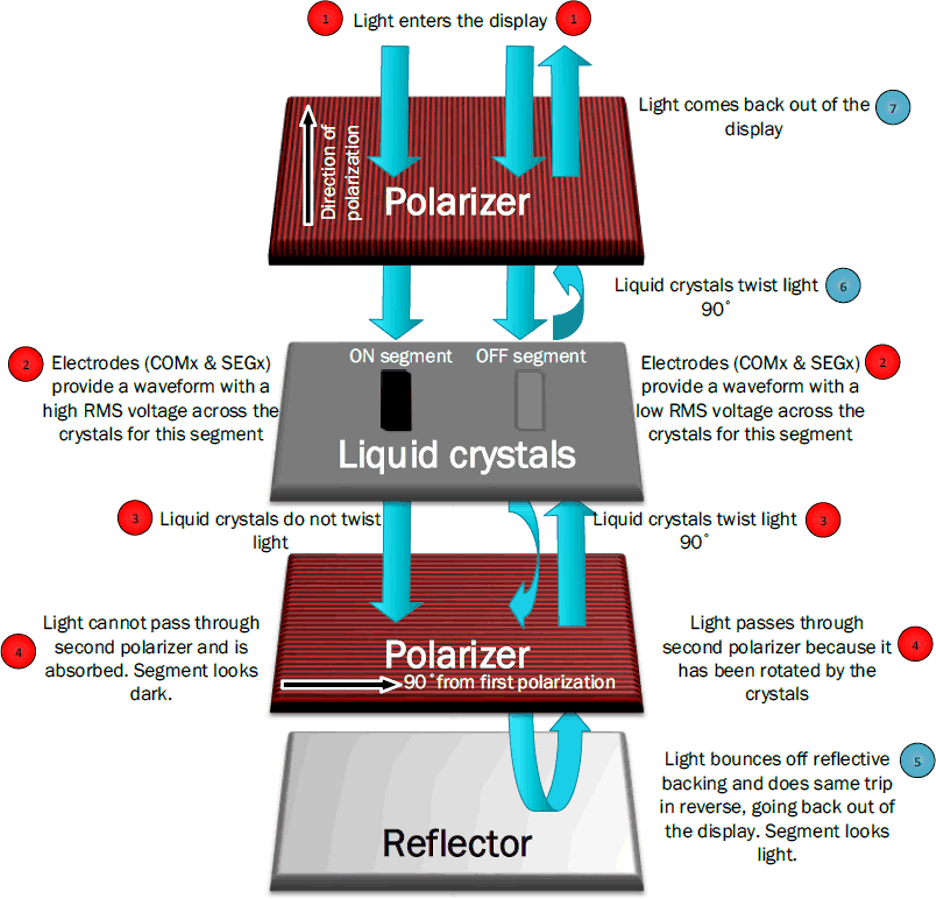
Figure 1 shows a simplified version of the structure of a segment LCD display. Essentially it consists of two polarizers rotated 90 degrees from each other to polarize light coming into the display, liquid crystals between the polarizers with electrodes to apply a charge, and a reflective backing to reflect light that gets through all the layers of the display.
 Figure 1. Segmented LCD Structure and Theory
 When no charge is applied to the electrodes for a particular segment, the segment is "off" or gray. In this normal state, the liquid crystals have a twisted structure that turns the light 90 degrees. So when no charge is applied: first, light comes in the first polarizer and comes out polarized in one direction. Then, the crystals turn the light 90 degrees as it passes through them – this allows the light to be able to pass through the second polarizer because it is rotated compared to the first one. Finally the light reflects off the reflective backing and does the same path in reverse. Because the light is reflected back, it looks light or gray.
When a charge is applied to the electrodes for a segment, the segment is "on" or black. In this charged state the crystals untwist, so they do not turn the light as it passes through them. So when a charge is applied: first, light comes in the first polarizer and comes out polarized in one direction. Then, the crystals simply allow the light to pass straight through without turning it this time. Because the second polarizer is at 90 degrees from the first one, the light is not able to pass through and is instead absorbed. This makes the segment look dark.