SLAA991 December 2020 TMUXHS4212
2 Major Parameters of Multiplexers
2.1 Ron resistance
One of the major parameters of analog multiplexers is On resistance. On-resistance (RON) is the resistance of the multiplexers path between the drain and source terminal when the multiplexer is closed. Ideally, RON needs to be kept as low as possible in order to keep the signal loss and propagation delays to be small. The On resistance value of the multiplexer translates into multiple performance characteristics of a signal multiplexer. For example, RON impacts the multiplexer’s power consumption, propagation delay, and the bandwidth of the signals that can pass through the multiplexer without distortion. In most cases, lower RON values are preferred in order to achieve optimal design.
2.2 Bandwidth
An analog multiplexer also has many ac specifications, such as bandwidth and insertion loss. Bandwidth is an important parameter to characterize the performance of many electrical systems. The term bandwidth refers to the pass band width of a filter, and in the case of a low-pass filter, the bandwidth is equal to the –3 dB frequency and indicates the upper limit of the frequency of signals passing through the multiplexers. Understanding the bandwidth capability of a signal multiplexer helps to determine if a multiplexer meets the performance requirements of the target application. A good rule of thumb is BW should be greater than or equal to 1.5 or 2 times Nyquist frequency.
2.3 Insertion Loss and Return Loss
Other important AC parameters are insertion loss and return loss. At high frequency, signal loss produces signal attenuation and distortion; the signal will be attenuated by conductor resistance and leakage in the material. The design of high-speed circuits therefore requires a knowledge of not only BW and Ron resistor, but also the dielectric constant and loss parameter.
Insertion loss and return loss are widely used terms in the field of microwave technologies. They play an important role in designing and development of high-speed devices such as filters, multiplexers. Insertion loss and return loss are what is used in cascading multiplexer’s analysis.
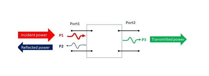
So what are Insertion loss and return loss? Technically, when some system or circuit is inserted between a source and a load, some of the signal power from the source is dissipated through the circuit components due to their resistive nature that results in losses. Therefore, not all the transmitted signal power is transferred to the load. The losses between the incident power and the transmitted power is called insertion Loss. Likewise, the difference between the incident power and the reflected power is called return loss.
 Figure 2-1 Two Ports Network.
 Insertion loss and return loss are linked with the scattering perimeters when the source and the load of the system is matched to the same reference impedance (say 50 Ohms). S parameters are the modern way of analyzing N-port networks. It is very helpful in optimizing the circuit to its best. It is capable of determining even smaller return loss and insertion loss in the form of s-parameters namely S11, S22, S12, S21:
-
S12 = forward transmission coefficient
-
S21 = reverse transmission coefficient
-
S11 = input reflection coefficient
-
S22 = output reflection coefficient