SLAAEB3A May 2023 – July 2024 MSPM0G3507 , MSPM0L1106 , MSPM0L1306
PRODUCTION DATA
2 Hardware Connection
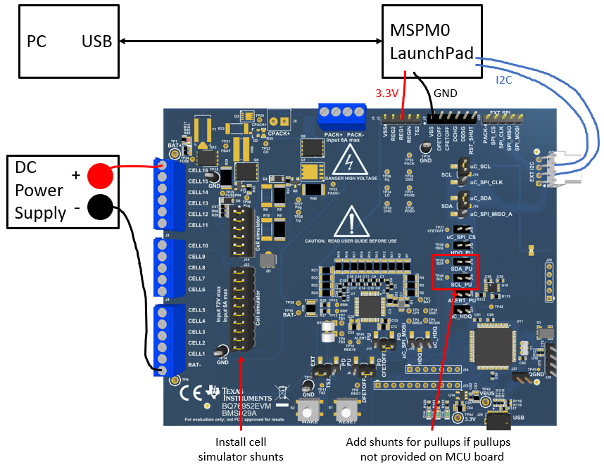
The I2C communication sample code implemented in this application note is based on the BQ76952EVM and MSPM0 LaunchPad™ (LP-MSPM0L1306 and LP-MSPM0G3507). MSPM0 acts as the I2C controller and BQ76952 acts as the peripheral. Figure 2-1 shows the simple system block diagram.
 Figure 2-1 System Block Diagram
For BQ76952EVM, check the BQ76952 chip by bringing the chip up with the onboard MCU (EV2400). Download the latest version of BQSTUDIO (the BQSTUDIO-TEST version) and follow the steps in the quick start section of EVM User Guide.
- Connect 10-72V DC power supply capable of 250mA minimum between the BAT- and CELL16 terminals of EVM to power the device.
- Connect the USB cable from micro-USB connector on the EVM to the PC. When this is connected, three green LEDs light up.
- Check the BQStudio Dashboard on the left side of BQStudio window. The dashboard indicates whether the onboard MCU is connected and which firmware version is being used. The dashboard also indicates whether the BQ76952 device is communicating successfully.
After confirming the BQ76952EVM board works successfully, start setting up the I2C bridge between MSPM0 and BQ769x2. If the USB on BQ769x2 EVM is not powered, remember to remove the connectors on uC_SCL(J19) and uC_SDA(J16).
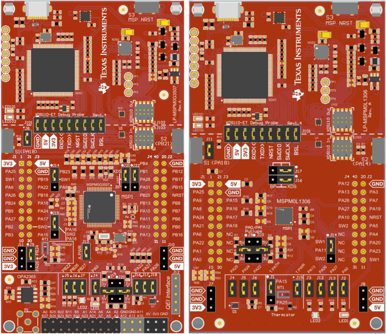
For MSPM0L1306 and MSPM0G3507 LaunchPad, PA1 is configured as the SCL pin, and PA0 is configured as the SDA pin. The LaunchPad is powered using the USB port on the host computer. Table 2-1 shows the signal and power connections between the two EVMs.
 Figure 2-2 LP-MSPM0G3507 and LP-MSPM0L1306
Hardware Board
Figure 2-2 LP-MSPM0G3507 and LP-MSPM0L1306
Hardware Board| Connection Type | Connection Name | LP-MSPM0L1306 Pin Number : Pin Name |
LP-MSPM0G3507 Pin Number : Pin Name |
BQ76952EVM Pin Number : Pin Name |
|---|---|---|---|---|
| I2C Interface | I2C : SCL | PA.1 : I2C0_SCL | PA.1 : I2C0_SCL | J17-2 : P26 |
| I2C : SDA | PA.0 : I2C0_SDA | PA.0 : I2C0_SDA | J17-3 : P27 | |
| Power connections | Power : 3.3V | J1-1 | J1-1 | J2-3 : REG1 |
| Power : Ground | J1-22 | J1-22 | J5-1 : VSS |
In the I2C interface, besides the connection of SCL and SDA, there are pullup methods on both boards. Select one EVM to pull up the SDA and SCL based on the actual situation.
Short J15 and J18 can pull up the SDA and SCL in the BQ76952EVM. The default value of the pullup resistor is 10kΩ. Adjust the resistor according the I2C bus speed. Figure 2-3 shows the pullup jumper diagram on BQ76952EVM.
 Figure 2-3 3.3V Pullup for SDA and SCL on
BQ76952EVM
Figure 2-3 3.3V Pullup for SDA and SCL on
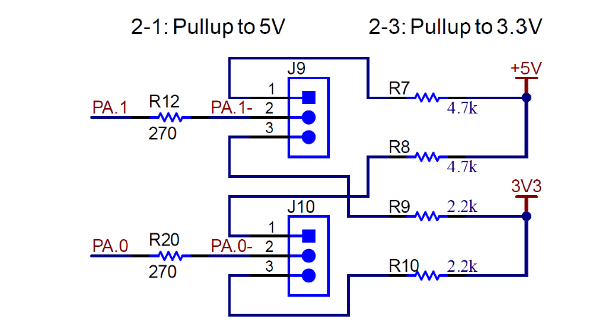
BQ76952EVMFor the LaunchPad, shorting J9-2-3 and J10-2-3 on LP-MSPM0L1306 or J19-1-2 and J20-1-2 on LP-MSPM0G3507 can pullup the SDA and SCL. The default value of the pullup resistor is 2.2kΩ. The value can also be adjusted according the I2C bus speed. Figure 2-4 shows the pullup jumper diagram on MSPM0L1306 LaunchPad.
 Figure 2-4 3.3V Pullup for SDA and SCL on
MSPM0L1306
Figure 2-4 3.3V Pullup for SDA and SCL on
MSPM0L1306Refer to the BQ76952EVM User’s Guide and LP-MSPM0L1306 LaunchPad User’s Guide or LP-MSPM0G3507 LaunchPad User's Guide for instructions to the other parts that are not mentioned.