SLAU367P October 2012 – April 2020 MSP430FR5041 , MSP430FR5043 , MSP430FR50431 , MSP430FR5847 , MSP430FR58471 , MSP430FR5848 , MSP430FR5849 , MSP430FR5857 , MSP430FR5858 , MSP430FR5859 , MSP430FR5867 , MSP430FR58671 , MSP430FR5868 , MSP430FR5869 , MSP430FR5870 , MSP430FR5872 , MSP430FR58721 , MSP430FR5887 , MSP430FR5888 , MSP430FR5889 , MSP430FR58891 , MSP430FR5922 , MSP430FR59221 , MSP430FR5947 , MSP430FR59471 , MSP430FR5948 , MSP430FR5949 , MSP430FR5957 , MSP430FR5958 , MSP430FR5959 , MSP430FR5962 , MSP430FR5964 , MSP430FR5967 , MSP430FR5968 , MSP430FR5969 , MSP430FR5969-SP , MSP430FR59691 , MSP430FR5970 , MSP430FR5972 , MSP430FR59721 , MSP430FR5986 , MSP430FR5987 , MSP430FR5988 , MSP430FR5989 , MSP430FR5989-EP , MSP430FR59891 , MSP430FR5992 , MSP430FR5994 , MSP430FR59941 , MSP430FR6005 , MSP430FR6007 , MSP430FR6035 , MSP430FR6037 , MSP430FR60371 , MSP430FR6041 , MSP430FR6043 , MSP430FR60431 , MSP430FR6045 , MSP430FR6047 , MSP430FR60471 , MSP430FR6820 , MSP430FR6822 , MSP430FR68221 , MSP430FR6870 , MSP430FR6872 , MSP430FR68721 , MSP430FR6877 , MSP430FR6879 , MSP430FR68791 , MSP430FR6887 , MSP430FR6888 , MSP430FR6889 , MSP430FR68891 , MSP430FR6920 , MSP430FR6922 , MSP430FR69221 , MSP430FR6927 , MSP430FR69271 , MSP430FR6928 , MSP430FR6970 , MSP430FR6972 , MSP430FR69721 , MSP430FR6977 , MSP430FR6979 , MSP430FR69791 , MSP430FR6987 , MSP430FR6988 , MSP430FR6989 , MSP430FR69891
30.3.4 Automatic Baud-Rate Detection
When UCMODEx = 11, UART mode with automatic baud-rate detection is selected. For automatic baud-rate detection, a data frame is preceded by a synchronization sequence that consists of a break and a synch field. A break is detected when 11 or more continuous zeros (spaces) are received. If the length of the break exceeds 21 bit times, the break timeout error flag UCBTOE is set. The eUSCI_A cannot transmit data while receiving the break/sync field. The synch field follows the break as shown in Figure 30-5.
 Figure 30-5 Auto Baud-Rate Detection – Break/Synch Sequence
 For LIN conformance, the character format should be set to eight data bits, LSB first, no parity, and one stop bit. No address bit is available.
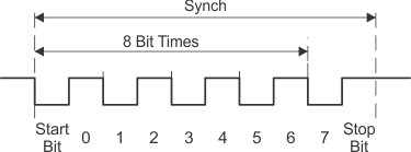
The synch field consists of the data 055h inside a byte field (see Figure 30-6). The synchronization is based on the time measurement between the first falling edge and the last falling edge of the pattern. The transmit baud-rate generator is used for the measurement if automatic baud-rate detection is enabled by setting UCABDEN. Otherwise, the pattern is received but not measured. The result of the measurement is transferred into the baud-rate control registers (UCAxBRW and UCAxMCTLW). If the length of the synch field exceeds the measurable time, the synch timeout error flag UCSTOE is set. The result can be read after the receive interrupt flag UCRXIFG is set.
 Figure 30-6 Auto Baud-Rate Detection – Synch Field
 The UCDORM bit is used to control data reception in this mode. When UCDORM is set, all characters are received but not transferred into the UCAxRXBUF, and interrupts are not generated. When a break/synch field is detected, the UCBRK flag is set. The character following the break/synch field is transferred into UCAxRXBUF and the UCRXIFG interrupt flag is set. Any applicable error flag is also set. If the UCBRKIE bit is set, reception of the break/synch sets the UCRXIFG. The UCBRK bit is reset by user software or by reading the receive buffer UCAxRXBUF.
When a break/synch field is received, user software must reset UCDORM to continue receiving data. If UCDORM remains set, only the character after the next reception of a break/synch field is received. The UCDORM bit is not modified by the eUSCI_A hardware automatically.
When UCDORM = 0, all received characters set the receive interrupt flag UCRXIFG. If UCDORM is cleared during the reception of a character, the receive interrupt flag is set after the reception is complete.
The counter used to detect the baud rate is limited to 0FFFFh (216) counts. This means the minimum baud rate detectable is 244 baud in oversampling mode and 15 baud in low-frequency mode. The highest detectable baud rate is 1 Mbaud.
The automatic baud-rate detection mode can be used in a full-duplex communication system with some restrictions. The eUSCI_A cannot transmit data while receiving the break/sync field and, if a 0h byte with framing error is received, any data transmitted during this time is corrupted. The latter case can be discovered by checking the received data and the UCFE bit.