SLAU367P October 2012 – April 2020 MSP430FR5041 , MSP430FR5043 , MSP430FR50431 , MSP430FR5847 , MSP430FR58471 , MSP430FR5848 , MSP430FR5849 , MSP430FR5857 , MSP430FR5858 , MSP430FR5859 , MSP430FR5867 , MSP430FR58671 , MSP430FR5868 , MSP430FR5869 , MSP430FR5870 , MSP430FR5872 , MSP430FR58721 , MSP430FR5887 , MSP430FR5888 , MSP430FR5889 , MSP430FR58891 , MSP430FR5922 , MSP430FR59221 , MSP430FR5947 , MSP430FR59471 , MSP430FR5948 , MSP430FR5949 , MSP430FR5957 , MSP430FR5958 , MSP430FR5959 , MSP430FR5962 , MSP430FR5964 , MSP430FR5967 , MSP430FR5968 , MSP430FR5969 , MSP430FR5969-SP , MSP430FR59691 , MSP430FR5970 , MSP430FR5972 , MSP430FR59721 , MSP430FR5986 , MSP430FR5987 , MSP430FR5988 , MSP430FR5989 , MSP430FR5989-EP , MSP430FR59891 , MSP430FR5992 , MSP430FR5994 , MSP430FR59941 , MSP430FR6005 , MSP430FR6007 , MSP430FR6035 , MSP430FR6037 , MSP430FR60371 , MSP430FR6041 , MSP430FR6043 , MSP430FR60431 , MSP430FR6045 , MSP430FR6047 , MSP430FR60471 , MSP430FR6820 , MSP430FR6822 , MSP430FR68221 , MSP430FR6870 , MSP430FR6872 , MSP430FR68721 , MSP430FR6877 , MSP430FR6879 , MSP430FR68791 , MSP430FR6887 , MSP430FR6888 , MSP430FR6889 , MSP430FR68891 , MSP430FR6920 , MSP430FR6922 , MSP430FR69221 , MSP430FR6927 , MSP430FR69271 , MSP430FR6928 , MSP430FR6970 , MSP430FR6972 , MSP430FR69721 , MSP430FR6977 , MSP430FR6979 , MSP430FR69791 , MSP430FR6987 , MSP430FR6988 , MSP430FR6989 , MSP430FR69891
37.2.3 ESI Pre-Processing and State Storage
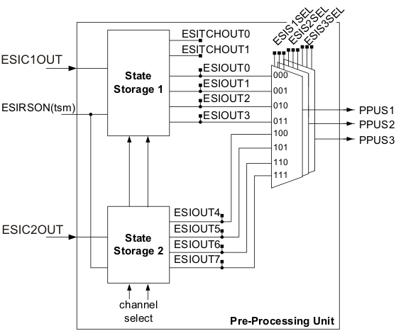
The Pre-Processing Unit (PPU) stores the measurement results of a TSM sequence. Beside this it also allows to select up to three signals that are processed by the Processing State Machine (PSM).
Up to four regular measurements and two test insertion measurements could sequentially be done within one TSM sequence. When ESIRSON(tsm) is high the comparator output signal is latched in the PPU's State Storage block. The State Storage consist of several latches. The output of these latches can be read from the ESIOUTx and ESITCHOUTx bits located in ESIPPU control register. Each input channel has its own latch. The ESICHx(tsm), ESITCH0x, or ESITCH1x bits define which of the latches is used.
The block diagram of the Pre-Processing Unit is shown in Figure 37-11.
 Figure 37-11 Pre-Processing Unit