SLAU367P October 2012 – April 2020 MSP430FR5041 , MSP430FR5043 , MSP430FR50431 , MSP430FR5847 , MSP430FR58471 , MSP430FR5848 , MSP430FR5849 , MSP430FR5857 , MSP430FR5858 , MSP430FR5859 , MSP430FR5867 , MSP430FR58671 , MSP430FR5868 , MSP430FR5869 , MSP430FR5870 , MSP430FR5872 , MSP430FR58721 , MSP430FR5887 , MSP430FR5888 , MSP430FR5889 , MSP430FR58891 , MSP430FR5922 , MSP430FR59221 , MSP430FR5947 , MSP430FR59471 , MSP430FR5948 , MSP430FR5949 , MSP430FR5957 , MSP430FR5958 , MSP430FR5959 , MSP430FR5962 , MSP430FR5964 , MSP430FR5967 , MSP430FR5968 , MSP430FR5969 , MSP430FR5969-SP , MSP430FR59691 , MSP430FR5970 , MSP430FR5972 , MSP430FR59721 , MSP430FR5986 , MSP430FR5987 , MSP430FR5988 , MSP430FR5989 , MSP430FR5989-EP , MSP430FR59891 , MSP430FR5992 , MSP430FR5994 , MSP430FR59941 , MSP430FR6005 , MSP430FR6007 , MSP430FR6035 , MSP430FR6037 , MSP430FR60371 , MSP430FR6041 , MSP430FR6043 , MSP430FR60431 , MSP430FR6045 , MSP430FR6047 , MSP430FR60471 , MSP430FR6820 , MSP430FR6822 , MSP430FR68221 , MSP430FR6870 , MSP430FR6872 , MSP430FR68721 , MSP430FR6877 , MSP430FR6879 , MSP430FR68791 , MSP430FR6887 , MSP430FR6888 , MSP430FR6889 , MSP430FR68891 , MSP430FR6920 , MSP430FR6922 , MSP430FR69221 , MSP430FR6927 , MSP430FR69271 , MSP430FR6928 , MSP430FR6970 , MSP430FR6972 , MSP430FR69721 , MSP430FR6977 , MSP430FR6979 , MSP430FR69791 , MSP430FR6987 , MSP430FR6988 , MSP430FR6989 , MSP430FR69891
37.2.2 ESI Timing State Machine
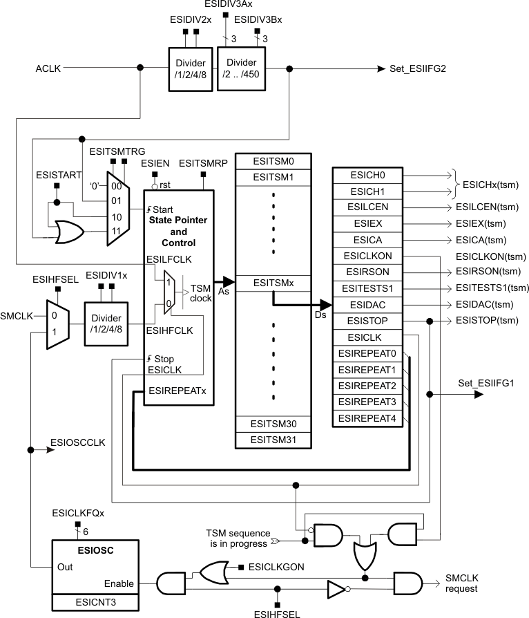
The TSM is a sequential state machine that cycles through the ESITSMx registers and controls the analog front end and sensor excitation automatically with no CPU intervention. The states are defined within a 32 x 16-bit memory, ESITSM0 to ESITSM31. The ESIEN bit enables the TSM. The ESI uses ACLK as its source for the low frequency clock signal ESILFCLK. When ESIEN = 0, the ACLK input divider, the TSM start flip-flop, and the TSM outputs are reset and the internal oscillator is stopped. The TSM block diagram is shown in Figure 37-8.
A TSM sequence begins at ESITSM0 and ends when the TSM encounters a ESITSMx state with a set ESITSTOP bit. When a state with a set ESISTOP bit is reached, the state counter is reset to zero and state processing stops. State processing re-starts at ESITSM0 with a software trigger (setting the ESISTART control bit), the next start condition when ESITSMRP = 0, or immediately when ESITSMRP = 1
After generation of the ESISTOP(tsm) pulse, the timing state machine will load and maintain the conditions defined in ESITSM0. For the case an LC sensor is used the ESILCEN(tsm) bit should be reset in ESITSM0 to ensure that all LC oscillators are shorted (damped) while no measurement sequence is in progress.
In case a TSM sequence is started with a software trigger, the ESISTART control bit is automatically cleared as soon as a TSM sequence is completed and the system is again in idle mode (ESITSM0 settings are used in idle mode).
 Figure 37-8 Timing State Machine Block Diagram