SLAU367P October 2012 – April 2020 MSP430FR5041 , MSP430FR5043 , MSP430FR50431 , MSP430FR5847 , MSP430FR58471 , MSP430FR5848 , MSP430FR5849 , MSP430FR5857 , MSP430FR5858 , MSP430FR5859 , MSP430FR5867 , MSP430FR58671 , MSP430FR5868 , MSP430FR5869 , MSP430FR5870 , MSP430FR5872 , MSP430FR58721 , MSP430FR5887 , MSP430FR5888 , MSP430FR5889 , MSP430FR58891 , MSP430FR5922 , MSP430FR59221 , MSP430FR5947 , MSP430FR59471 , MSP430FR5948 , MSP430FR5949 , MSP430FR5957 , MSP430FR5958 , MSP430FR5959 , MSP430FR5962 , MSP430FR5964 , MSP430FR5967 , MSP430FR5968 , MSP430FR5969 , MSP430FR5969-SP , MSP430FR59691 , MSP430FR5970 , MSP430FR5972 , MSP430FR59721 , MSP430FR5986 , MSP430FR5987 , MSP430FR5988 , MSP430FR5989 , MSP430FR5989-EP , MSP430FR59891 , MSP430FR5992 , MSP430FR5994 , MSP430FR59941 , MSP430FR6005 , MSP430FR6007 , MSP430FR6035 , MSP430FR6037 , MSP430FR60371 , MSP430FR6041 , MSP430FR6043 , MSP430FR60431 , MSP430FR6045 , MSP430FR6047 , MSP430FR60471 , MSP430FR6820 , MSP430FR6822 , MSP430FR68221 , MSP430FR6870 , MSP430FR6872 , MSP430FR68721 , MSP430FR6877 , MSP430FR6879 , MSP430FR68791 , MSP430FR6887 , MSP430FR6888 , MSP430FR6889 , MSP430FR68891 , MSP430FR6920 , MSP430FR6922 , MSP430FR69221 , MSP430FR6927 , MSP430FR69271 , MSP430FR6928 , MSP430FR6970 , MSP430FR6972 , MSP430FR69721 , MSP430FR6977 , MSP430FR6979 , MSP430FR69791 , MSP430FR6987 , MSP430FR6988 , MSP430FR6989 , MSP430FR69891
7.8 FRAM Power Control
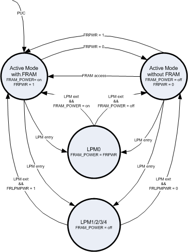
The FRAM controller can disable the power supply for the FRAM array. By setting FRPWR = 0, the FRAM array supply is disabled. Register accesses in the FRAM controller are still possible. Memory accesses pointing into the FRAM address space automatically reset the FRPWR = 1 and re-enable the power supply of the FRAM. A second control bit, FRLPMPWR, delays the power-up of the FRAM after LPM exit. With FRLPMPWR = 1, the FRAM is activated directly on exit from LPM. FRLPMPWR = 0 delays the activation of the FRAM to the first access into the FRAM address space. For LPM0, the FRAM power state during LPM0 is determined from the previous state in active mode. If FRAM power is disabled, a memory access automatically inserts wait states to ensure sufficient timing for the FRAM power-up and access. Access to FRAM that can be served from cache does not change the power state of the FRAM power control.
A PUC reset forces the state machine to Active mode with FRAM enabled. The CPU must execute from RAM to clear the FRPWR bit for turning off power to FRAM.
Figure 7-2 shows the activation flow of the FRAM controller.
 Figure 7-2 FRAM Power Control Diagram