SLAU367P October 2012 – April 2020 MSP430FR5041 , MSP430FR5043 , MSP430FR50431 , MSP430FR5847 , MSP430FR58471 , MSP430FR5848 , MSP430FR5849 , MSP430FR5857 , MSP430FR5858 , MSP430FR5859 , MSP430FR5867 , MSP430FR58671 , MSP430FR5868 , MSP430FR5869 , MSP430FR5870 , MSP430FR5872 , MSP430FR58721 , MSP430FR5887 , MSP430FR5888 , MSP430FR5889 , MSP430FR58891 , MSP430FR5922 , MSP430FR59221 , MSP430FR5947 , MSP430FR59471 , MSP430FR5948 , MSP430FR5949 , MSP430FR5957 , MSP430FR5958 , MSP430FR5959 , MSP430FR5962 , MSP430FR5964 , MSP430FR5967 , MSP430FR5968 , MSP430FR5969 , MSP430FR5969-SP , MSP430FR59691 , MSP430FR5970 , MSP430FR5972 , MSP430FR59721 , MSP430FR5986 , MSP430FR5987 , MSP430FR5988 , MSP430FR5989 , MSP430FR5989-EP , MSP430FR59891 , MSP430FR5992 , MSP430FR5994 , MSP430FR59941 , MSP430FR6005 , MSP430FR6007 , MSP430FR6035 , MSP430FR6037 , MSP430FR60371 , MSP430FR6041 , MSP430FR6043 , MSP430FR60431 , MSP430FR6045 , MSP430FR6047 , MSP430FR60471 , MSP430FR6820 , MSP430FR6822 , MSP430FR68221 , MSP430FR6870 , MSP430FR6872 , MSP430FR68721 , MSP430FR6877 , MSP430FR6879 , MSP430FR68791 , MSP430FR6887 , MSP430FR6888 , MSP430FR6889 , MSP430FR68891 , MSP430FR6920 , MSP430FR6922 , MSP430FR69221 , MSP430FR6927 , MSP430FR69271 , MSP430FR6928 , MSP430FR6970 , MSP430FR6972 , MSP430FR69721 , MSP430FR6977 , MSP430FR6979 , MSP430FR69791 , MSP430FR6987 , MSP430FR6988 , MSP430FR6989 , MSP430FR69891
37.2.8.1.2 LC-Sensor Envelope Test
The envelop test measures the decay time of the oscillations after sensor excitation. The oscillation envelope is created by the diodes and RC filters. The DAC is used to set the reference level for the comparator, and the comparator detects if the oscillation envelop is above or below the reference level. The comparator and AFE outputs are connected to Timer_A and the capture/compare registers for Timer_A are used to time the decay of the oscillation envelope. The PSM is not used for the envelope test.
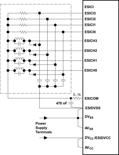
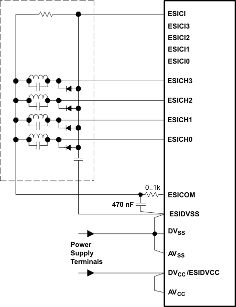
When the sensors are connected to the individual ESICIx inputs as shown in Figure 37-17, the comparator reference level can be adjusted for each sensor individually. When all sensors are connected to the ESICI input as shown in Figure 37-18, only one comparator reference level is set for all sensors.
 Figure 37-17 LC Sensor Connections For The Envelope Test
  Figure 37-18 LC Sensor Connections For the Envelope Test