SLAU367P October 2012 – April 2020 MSP430FR5041 , MSP430FR5043 , MSP430FR50431 , MSP430FR5847 , MSP430FR58471 , MSP430FR5848 , MSP430FR5849 , MSP430FR5857 , MSP430FR5858 , MSP430FR5859 , MSP430FR5867 , MSP430FR58671 , MSP430FR5868 , MSP430FR5869 , MSP430FR5870 , MSP430FR5872 , MSP430FR58721 , MSP430FR5887 , MSP430FR5888 , MSP430FR5889 , MSP430FR58891 , MSP430FR5922 , MSP430FR59221 , MSP430FR5947 , MSP430FR59471 , MSP430FR5948 , MSP430FR5949 , MSP430FR5957 , MSP430FR5958 , MSP430FR5959 , MSP430FR5962 , MSP430FR5964 , MSP430FR5967 , MSP430FR5968 , MSP430FR5969 , MSP430FR5969-SP , MSP430FR59691 , MSP430FR5970 , MSP430FR5972 , MSP430FR59721 , MSP430FR5986 , MSP430FR5987 , MSP430FR5988 , MSP430FR5989 , MSP430FR5989-EP , MSP430FR59891 , MSP430FR5992 , MSP430FR5994 , MSP430FR59941 , MSP430FR6005 , MSP430FR6007 , MSP430FR6035 , MSP430FR6037 , MSP430FR60371 , MSP430FR6041 , MSP430FR6043 , MSP430FR60431 , MSP430FR6045 , MSP430FR6047 , MSP430FR60471 , MSP430FR6820 , MSP430FR6822 , MSP430FR68221 , MSP430FR6870 , MSP430FR6872 , MSP430FR68721 , MSP430FR6877 , MSP430FR6879 , MSP430FR68791 , MSP430FR6887 , MSP430FR6888 , MSP430FR6889 , MSP430FR68891 , MSP430FR6920 , MSP430FR6922 , MSP430FR69221 , MSP430FR6927 , MSP430FR69271 , MSP430FR6928 , MSP430FR6970 , MSP430FR6972 , MSP430FR69721 , MSP430FR6977 , MSP430FR6979 , MSP430FR69791 , MSP430FR6987 , MSP430FR6988 , MSP430FR6989 , MSP430FR69891
31.3.3 Master Mode
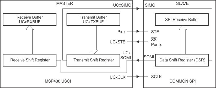
 Figure 31-2 eUSCI Master and External Slave (UCSTEM = 0)
 Figure 31-2 shows the eUSCI as a master in both 3-pin and 4-pin configurations. The eUSCI initiates data transfer when data is moved to the transmit data buffer UCxTXBUF. The UCxTXBUF data is moved to the transmit (TX) shift register when the TX shift register is empty, initiating data transfer on UCxSIMO starting with either the MSB or LSB, depending on the UCMSB setting. Data on UCxSOMI is shifted into the receive shift register on the opposite clock edge. When the character is received, the receive data is moved from the receive (RX) shift register to the received data buffer UCxRXBUF and the receive interrupt flag UCRXIFG is set, indicating the RX/TX operation is complete.
A set transmit interrupt flag, UCTXIFG, indicates that data has moved from UCxTXBUF to the TX shift register and UCxTXBUF is ready for new data. It does not indicate RX/TX completion.
To receive data into the eUSCI in master mode, data must be written to UCxTXBUF, because receive and transmit operations operate concurrently.
There two different options for configuring the eUSCI as a 4-pin master, which are described in the next sections:
- The fourth pin is used as input to prevent conflicts with other masters (UCSTEM = 0).
- The fourth pin is used as output to generate a slave enable signal (UCSTEM = 1).
The bit UCSTEM is used to select the corresponding mode.