SLAU367P October 2012 – April 2020 MSP430FR5041 , MSP430FR5043 , MSP430FR50431 , MSP430FR5847 , MSP430FR58471 , MSP430FR5848 , MSP430FR5849 , MSP430FR5857 , MSP430FR5858 , MSP430FR5859 , MSP430FR5867 , MSP430FR58671 , MSP430FR5868 , MSP430FR5869 , MSP430FR5870 , MSP430FR5872 , MSP430FR58721 , MSP430FR5887 , MSP430FR5888 , MSP430FR5889 , MSP430FR58891 , MSP430FR5922 , MSP430FR59221 , MSP430FR5947 , MSP430FR59471 , MSP430FR5948 , MSP430FR5949 , MSP430FR5957 , MSP430FR5958 , MSP430FR5959 , MSP430FR5962 , MSP430FR5964 , MSP430FR5967 , MSP430FR5968 , MSP430FR5969 , MSP430FR5969-SP , MSP430FR59691 , MSP430FR5970 , MSP430FR5972 , MSP430FR59721 , MSP430FR5986 , MSP430FR5987 , MSP430FR5988 , MSP430FR5989 , MSP430FR5989-EP , MSP430FR59891 , MSP430FR5992 , MSP430FR5994 , MSP430FR59941 , MSP430FR6005 , MSP430FR6007 , MSP430FR6035 , MSP430FR6037 , MSP430FR60371 , MSP430FR6041 , MSP430FR6043 , MSP430FR60431 , MSP430FR6045 , MSP430FR6047 , MSP430FR60471 , MSP430FR6820 , MSP430FR6822 , MSP430FR68221 , MSP430FR6870 , MSP430FR6872 , MSP430FR68721 , MSP430FR6877 , MSP430FR6879 , MSP430FR68791 , MSP430FR6887 , MSP430FR6888 , MSP430FR6889 , MSP430FR68891 , MSP430FR6920 , MSP430FR6922 , MSP430FR69221 , MSP430FR6927 , MSP430FR69271 , MSP430FR6928 , MSP430FR6970 , MSP430FR6972 , MSP430FR69721 , MSP430FR6977 , MSP430FR6979 , MSP430FR69791 , MSP430FR6987 , MSP430FR6988 , MSP430FR6989 , MSP430FR69891
2.1 Power Management Module (PMM) Introduction
PMM features include:
- Wide supply voltage (DVCC) range: 1.8 V to 3.6 V
- Generation of voltage for the device core (VCORE)
- Supply voltage supervisor (SVS) for DVCC
- Brownout reset (BOR)
- Software accessible power-fail indicators
- I/O protection during power-fail condition
The PMM manages all functions related to the power supply and its supervision for the device. Its primary functions are first to generate a supply voltage for the core logic, and second, provide several mechanisms for the supervision of the voltage applied to the device (DVCC).
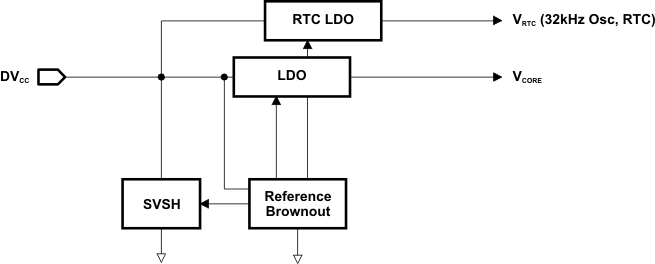
The PMM uses an integrated low-dropout voltage regulator (LDO) to produce a secondary core voltage (VCORE) from the primary one applied to the device (DVCC). In general, VCORE supplies the CPU, memories, and the digital modules, while DVCC supplies the I/Os and analog modules. The VCORE output is maintained using a dedicated voltage reference. The input or primary side of the regulator is referred to in this chapter as its high side. The output or secondary side is referred to in this chapter as its low side.
Figure 2-1 shows the block diagram of the PMM.
 Figure 2-1 PMM Block Diagram