SLAU367P October 2012 – April 2020 MSP430FR5041 , MSP430FR5043 , MSP430FR50431 , MSP430FR5847 , MSP430FR58471 , MSP430FR5848 , MSP430FR5849 , MSP430FR5857 , MSP430FR5858 , MSP430FR5859 , MSP430FR5867 , MSP430FR58671 , MSP430FR5868 , MSP430FR5869 , MSP430FR5870 , MSP430FR5872 , MSP430FR58721 , MSP430FR5887 , MSP430FR5888 , MSP430FR5889 , MSP430FR58891 , MSP430FR5922 , MSP430FR59221 , MSP430FR5947 , MSP430FR59471 , MSP430FR5948 , MSP430FR5949 , MSP430FR5957 , MSP430FR5958 , MSP430FR5959 , MSP430FR5962 , MSP430FR5964 , MSP430FR5967 , MSP430FR5968 , MSP430FR5969 , MSP430FR5969-SP , MSP430FR59691 , MSP430FR5970 , MSP430FR5972 , MSP430FR59721 , MSP430FR5986 , MSP430FR5987 , MSP430FR5988 , MSP430FR5989 , MSP430FR5989-EP , MSP430FR59891 , MSP430FR5992 , MSP430FR5994 , MSP430FR59941 , MSP430FR6005 , MSP430FR6007 , MSP430FR6035 , MSP430FR6037 , MSP430FR60371 , MSP430FR6041 , MSP430FR6043 , MSP430FR60431 , MSP430FR6045 , MSP430FR6047 , MSP430FR60471 , MSP430FR6820 , MSP430FR6822 , MSP430FR68221 , MSP430FR6870 , MSP430FR6872 , MSP430FR68721 , MSP430FR6877 , MSP430FR6879 , MSP430FR68791 , MSP430FR6887 , MSP430FR6888 , MSP430FR6889 , MSP430FR68891 , MSP430FR6920 , MSP430FR6922 , MSP430FR69221 , MSP430FR6927 , MSP430FR69271 , MSP430FR6928 , MSP430FR6970 , MSP430FR6972 , MSP430FR69721 , MSP430FR6977 , MSP430FR6979 , MSP430FR69791 , MSP430FR6987 , MSP430FR6988 , MSP430FR6989 , MSP430FR69891
4.3.1 Program Counter (PC)
The 20-bit program counter (PC, also called R0) points to the next instruction to be executed. Each instruction uses an even number of bytes (2, 4, 6, or 8 bytes), and the PC is incremented accordingly. Instruction accesses are performed on word boundaries, and the PC is aligned to even addresses. Figure 4-3 shows the PC.
 Figure 4-3 Program Counter
 The PC can be addressed with all instructions and addressing modes. A few examples:
MOV.W  #LABEL,PC  ; Branch to address LABEL (lower 64KB)

MOVA   #LABEL,PC  ; Branch to address LABEL (1MB memory)

MOV.W  LABEL,PC   ; Branch to address in word LABEL
                  ; (lower 64KB)

MOV.W  @R14,PC    ; Branch indirect to address in
                  ; R14 (lower 64KB)

ADDA   #4,PC      ; Skip 2 words (1MB memory)
The BR and CALL instructions reset the upper 4 PC bits to 0. Only addresses in the lower 64KB address range can be reached with the BR or CALL instruction. When branching or calling, addresses beyond the lower 64KB range can only be reached using the BRA or CALLA instructions. Also, any instruction to directly modify the PC does so according to the used addressing mode. For example, MOV.W #value,PC clears the upper 4 bits of the PC, because it is a .W instruction.
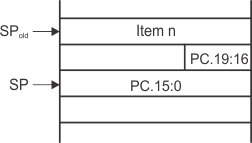
The PC is automatically stored on the stack with CALL (or CALLA) instructions and during an interrupt service routine. Figure 4-4 shows the storage of the PC with the return address after a CALLA instruction. A CALL instruction stores only bits 15:0 of the PC.
 Figure 4-4 PC Storage on the Stack for CALLA
 The RETA instruction restores bits 19:0 of the PC and adds 4 to the stack pointer (SP). The RET instruction restores bits 15:0 to the PC and adds 2 to the SP.