SLAU367P October 2012 – April 2020 MSP430FR5041 , MSP430FR5043 , MSP430FR50431 , MSP430FR5847 , MSP430FR58471 , MSP430FR5848 , MSP430FR5849 , MSP430FR5857 , MSP430FR5858 , MSP430FR5859 , MSP430FR5867 , MSP430FR58671 , MSP430FR5868 , MSP430FR5869 , MSP430FR5870 , MSP430FR5872 , MSP430FR58721 , MSP430FR5887 , MSP430FR5888 , MSP430FR5889 , MSP430FR58891 , MSP430FR5922 , MSP430FR59221 , MSP430FR5947 , MSP430FR59471 , MSP430FR5948 , MSP430FR5949 , MSP430FR5957 , MSP430FR5958 , MSP430FR5959 , MSP430FR5962 , MSP430FR5964 , MSP430FR5967 , MSP430FR5968 , MSP430FR5969 , MSP430FR5969-SP , MSP430FR59691 , MSP430FR5970 , MSP430FR5972 , MSP430FR59721 , MSP430FR5986 , MSP430FR5987 , MSP430FR5988 , MSP430FR5989 , MSP430FR5989-EP , MSP430FR59891 , MSP430FR5992 , MSP430FR5994 , MSP430FR59941 , MSP430FR6005 , MSP430FR6007 , MSP430FR6035 , MSP430FR6037 , MSP430FR60371 , MSP430FR6041 , MSP430FR6043 , MSP430FR60431 , MSP430FR6045 , MSP430FR6047 , MSP430FR60471 , MSP430FR6820 , MSP430FR6822 , MSP430FR68221 , MSP430FR6870 , MSP430FR6872 , MSP430FR68721 , MSP430FR6877 , MSP430FR6879 , MSP430FR68791 , MSP430FR6887 , MSP430FR6888 , MSP430FR6889 , MSP430FR68891 , MSP430FR6920 , MSP430FR6922 , MSP430FR69221 , MSP430FR6927 , MSP430FR69271 , MSP430FR6928 , MSP430FR6970 , MSP430FR6972 , MSP430FR69721 , MSP430FR6977 , MSP430FR6979 , MSP430FR69791 , MSP430FR6987 , MSP430FR6988 , MSP430FR6989 , MSP430FR69891
1.14.3.1 REF Calibration
Table 1-6 shows the REF calibration tags.
Table 1-6 REF Calibration Tags
| REF Calibration | TAG | 12h |
| Length | 06h | |
| Low Byte | CAL_ADC_12VREF_FACTOR | |
| High Byte | ||
| Low Byte | CAL_ADC_20VREF_FACTOR | |
| High Byte | ||
| Low Byte | CAL_ADC_25VREF_FACTOR | |
| High Byte |
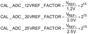
The calibration data for the REF module consists of three words, one word for each reference voltage available (1.2 V, 2.0 V, and 2.5 V). The reference voltages are measured at room temperature. The measured values are normalized by 1.2 V, 2.0 V, or 2.5 V before being stored into the TLV structure, as shown in Equation 2:

In this way, a conversion result is corrected by multiplying it with the CAL_12VREF_FACTOR (or CAL_20VREF_FACTOR, CAL_25VREF_FACTOR) and dividing the result by 215as shown in Equation 3 for each of the respective reference voltages:

In the following example, the integrated 1.2-V reference voltage is used during a conversion.
- Conversion result: 0x0100 = 256 decimal
- Reference voltage calibration factor (CAL_12VREF_FACTOR) : 0x7BBB
The following steps show how the ADC conversion result can be corrected:
- Multiply the conversion result by 2 (this step simplifies the final division): 0x0100 x 0x0002 = 0x0200
- Multiply the result by CAL_12VREF_FACTOR: 0x200 x 0x7FEE = 0x00F7_7600
- Divide the result by 216: 0x00F7_7600 / 0x0001_0000 = 0x0000_00F7 = 247 decimal