SLAU367P October 2012 – April 2020 MSP430FR5041 , MSP430FR5043 , MSP430FR50431 , MSP430FR5847 , MSP430FR58471 , MSP430FR5848 , MSP430FR5849 , MSP430FR5857 , MSP430FR5858 , MSP430FR5859 , MSP430FR5867 , MSP430FR58671 , MSP430FR5868 , MSP430FR5869 , MSP430FR5870 , MSP430FR5872 , MSP430FR58721 , MSP430FR5887 , MSP430FR5888 , MSP430FR5889 , MSP430FR58891 , MSP430FR5922 , MSP430FR59221 , MSP430FR5947 , MSP430FR59471 , MSP430FR5948 , MSP430FR5949 , MSP430FR5957 , MSP430FR5958 , MSP430FR5959 , MSP430FR5962 , MSP430FR5964 , MSP430FR5967 , MSP430FR5968 , MSP430FR5969 , MSP430FR5969-SP , MSP430FR59691 , MSP430FR5970 , MSP430FR5972 , MSP430FR59721 , MSP430FR5986 , MSP430FR5987 , MSP430FR5988 , MSP430FR5989 , MSP430FR5989-EP , MSP430FR59891 , MSP430FR5992 , MSP430FR5994 , MSP430FR59941 , MSP430FR6005 , MSP430FR6007 , MSP430FR6035 , MSP430FR6037 , MSP430FR60371 , MSP430FR6041 , MSP430FR6043 , MSP430FR60431 , MSP430FR6045 , MSP430FR6047 , MSP430FR60471 , MSP430FR6820 , MSP430FR6822 , MSP430FR68221 , MSP430FR6870 , MSP430FR6872 , MSP430FR68721 , MSP430FR6877 , MSP430FR6879 , MSP430FR68791 , MSP430FR6887 , MSP430FR6888 , MSP430FR6889 , MSP430FR68891 , MSP430FR6920 , MSP430FR6922 , MSP430FR69221 , MSP430FR6927 , MSP430FR69271 , MSP430FR6928 , MSP430FR6970 , MSP430FR6972 , MSP430FR69721 , MSP430FR6977 , MSP430FR6979 , MSP430FR69791 , MSP430FR6987 , MSP430FR6988 , MSP430FR6989 , MSP430FR69891
37.2.4 TimerA Output Stage
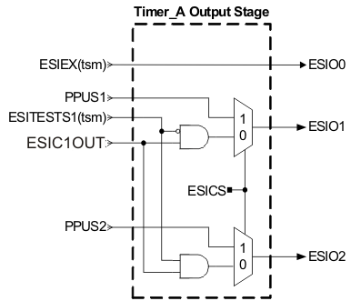
The comparator output of the analog front end AFE1, the ESIEX(tsm) signal, and two preprocessing unit outputs PPUS1 and PPUS2 are connected to a Timer_A's capture inputs through the ESI's Timer_A output stage, shown in Figure 37-12. There are two different modes that are selected by the ESICS bit. The Timer_A Output Stage provides the ESIOx signals to one of the device's Timer_A module. See the device-specific data sheet for connection of these signals.
 Figure 37-12 Timer_A Output Stage of the Analog Front End
 When ESICS = 0, the ESIEX(tsm) signal and the comparator output can be selected as inputs to different Timer_A capture/compare registers. This can be used to measure the time between excitation of a sensor and the last oscillation that passes through the comparator or to perform a slope A/D conversion.
When ESICS = 1, the ESIEX(tsm) signal and the output bits PPUS1 and PPUS2 from the PPU can be selected as inputs to Timer_A. This can be used to measure the duty cycle of PPUS1 or PPUS2.