SLAU367P October 2012 – April 2020 MSP430FR5041 , MSP430FR5043 , MSP430FR50431 , MSP430FR5847 , MSP430FR58471 , MSP430FR5848 , MSP430FR5849 , MSP430FR5857 , MSP430FR5858 , MSP430FR5859 , MSP430FR5867 , MSP430FR58671 , MSP430FR5868 , MSP430FR5869 , MSP430FR5870 , MSP430FR5872 , MSP430FR58721 , MSP430FR5887 , MSP430FR5888 , MSP430FR5889 , MSP430FR58891 , MSP430FR5922 , MSP430FR59221 , MSP430FR5947 , MSP430FR59471 , MSP430FR5948 , MSP430FR5949 , MSP430FR5957 , MSP430FR5958 , MSP430FR5959 , MSP430FR5962 , MSP430FR5964 , MSP430FR5967 , MSP430FR5968 , MSP430FR5969 , MSP430FR5969-SP , MSP430FR59691 , MSP430FR5970 , MSP430FR5972 , MSP430FR59721 , MSP430FR5986 , MSP430FR5987 , MSP430FR5988 , MSP430FR5989 , MSP430FR5989-EP , MSP430FR59891 , MSP430FR5992 , MSP430FR5994 , MSP430FR59941 , MSP430FR6005 , MSP430FR6007 , MSP430FR6035 , MSP430FR6037 , MSP430FR60371 , MSP430FR6041 , MSP430FR6043 , MSP430FR60431 , MSP430FR6045 , MSP430FR6047 , MSP430FR60471 , MSP430FR6820 , MSP430FR6822 , MSP430FR68221 , MSP430FR6870 , MSP430FR6872 , MSP430FR68721 , MSP430FR6877 , MSP430FR6879 , MSP430FR68791 , MSP430FR6887 , MSP430FR6888 , MSP430FR6889 , MSP430FR68891 , MSP430FR6920 , MSP430FR6922 , MSP430FR69221 , MSP430FR6927 , MSP430FR69271 , MSP430FR6928 , MSP430FR6970 , MSP430FR6972 , MSP430FR69721 , MSP430FR6977 , MSP430FR6979 , MSP430FR69791 , MSP430FR6987 , MSP430FR6988 , MSP430FR6989 , MSP430FR69891
21.5 Ultra-Low-Power Bias Mode
The ultra-low bias power mode suppresses the PLL operation during the hold-off delay phase on USS startup. Because the PLL and its clock tree operate at a high frequency, considerable energy savings can be achieved. Common utility flow meters that enter LPM3 or LPM3.5 between the measurements with turned off USSXT benefit in particular from that mode.
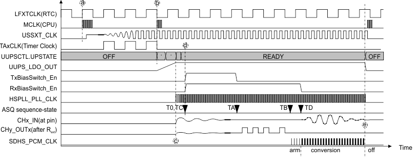
Figure 21-19 shows a typical use case with register mode or auto mode. The timing axis and the amplitudes in the diagram are not to scale. Following a very short summary of that theoretical use cases... .
After an RTC event at (a), the system wakes up from LPMx, runs boot code, configures the USS trimming, and enters application code. This turns on USSXT, prepares time-out on TimerA that is running from LFXTCLK, then the CPU enters LPMx.
At (b), the TimerA service routine starts the UUPS, and the CPU enters LPMx again.
At (c), the transducers and external circuits may show ringing due to power up and bias voltage enable. The signals settle then.
At (d) the HSPLL generates a clock with almost no remaining phase variations. Near TA, the transducers have settled and the regular sequence is started by generating pulses. At TB, well before the arrival of the signal, the SDHS and its clock is enabled. At TD, the data acquisition starts.
At (e), the sequence is completed. The interrupt service routine performs calculations and sets the system to LPMx again.
 Figure 21-19 Auto Mode and Register Mode Example
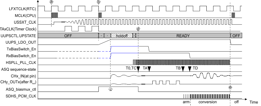
 Figure 21-20 shows a the use case with ultra-low-power bias mode. The timing axis and the amplitudes in the diagram are not to scale. The following is a short summary of that theoretical use case:
After an RTC event at (a), the system wakes up from LPMx, runs boot code, configures the USS trimming, and enters application code. This turns on USSXT, prepares time-out on TimerA that is running from LFXTCLK, and then the CPU enters LPMx.
At (b), the TimerA service routine starts the UUPS with hold-off delay, and the CPU enters LPMx again. The UUPS state machine starts up with suppressed HSPLL.
At (c), the transducers and external circuits may show ringing due to power up and bias voltages. The signals settle then.
At (d), the HSPLL generates a clock with almost no remaining phase variations. Near TA, the transducers have settled and the regular sequence is started by generating pulses. At TB, well before the arrival of the signal, the SDHS and its clock are enabled. At TD, the data acquisition starts.
At (e), the sequence is completed. The interrupt service routine perform calculations and sets the system to LPMx again.
The ASQ.mux control signal switches between both control register sets during power up. Both register sets require same values of the corresponding control bits for a smooth bias generation and handover.
 Figure 21-20 Ultra-Low-Power Bias Mode Example