SLAU416B January 2012 – November 2021 TLV62130 , TLV62130A , TLV62150 , TLV62150A
1.3.3 Loop Response Measurement
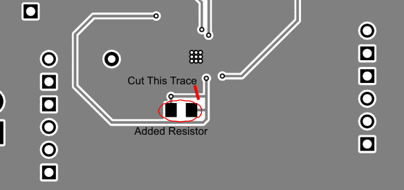
The loop response of the TLV621x0EVM-505 can be measured with two simple changes to the circuitry. First, install a 10-Ω resistor across the pads in the middle of the back of the PCB. The pads are spaced to allow installation of 0805- or 0603-sized resistors. Second, cut the trace between the via on the output voltage and the trace that connects to the VOS pin via. These changes are shown in Figure 1-1. With these changes, an ac signal (10-mV, peak-to-peak amplitude recommended) can be injected into the control loop across the added resistor.
 Figure 1-1 Loop Response Measurement Modification