SLAU723A October 2017 – October 2018 MSP432E401Y , MSP432E411Y
- 1
- 7
- 65
- 132
-
167
- 168
-
215
- 216
- 217
- 218
- 219
- 220
- 221
- 222
- 223
- 224
- 225
- 226
- 227
- 228
- 229
- 230
- 231
- 232
- 233
- 234
- 235
- 236
- 237
- 238
- 239
- 240
- 241
- 242
- 243
- 244
- 245
- 246
- 247
- 248
- 249
- 250
- 251
- 252
- 253
- 254
- 255
- 256
- 257
- 258
- 259
- 260
- 261
- 262
- 263
- 264
- 265
- 266
- 267
- 268
- 269
- 270
- 271
- 272
- 273
- 274
- 275
- 276
- 277
- 278
- 279
- 280
- 281
- 282
- 283
- 284
- 285
- 286
- 287
- 288
- 289
- 290
- 291
- 292
- 293
- 294
- 295
- 296
- 297
- 298
- 299
- 300
- 301
- 302
- 303
- 304
- 305
- 306
- 307
- 308
- 309
- 310
- 311
- 312
- 313
- 314
- 315
- 316
- 317
- 318
- 319
- 320
- 321
- 322
- 323
- 324
- 325
- 326
- 327
- 328
- 329
- 330
- 331
- 332
- 333
- 334
- 335
- 336
- 337
- 338
- 339
- 340
- 341
- 342
- 343
- 344
- 345
- 346
- 347
- 348
- 349
- 350
- 351
- 352
- 353
- 354
- 355
- 356
- 357
- 358
- 359
- 360
- 361
- 362
- 363
- 364
- 365
- 366
- 367
- 368
- 369
- 370
- 371
- 372
- 373
- 374
- 375
- 376
- 377
- 378
- 379
- 380
- 381
- 382
- 383
- 384
- 385
- 386
- 387
- 388
- 389
- 390
- 391
- 392
- 393
- 394
- 395
- 396
- 397
- 398
- 399
- 400
- 401
- 402
- 403
- 404
- 405
- 406
- 408
- 415
- 482
- 564
- 643
- 715
- 791
- 841
- 855
- 870
-
917
- 918
- 919
- 920
- 1002
- 1017
-
1021
- 1022
- 1023
- 1024
- 1025
- 1026
- 1027
- 1028
- 1029
- 1030
- 1031
- 1032
- 1033
- 1034
- 1035
- 1036
- 1037
- 1038
- 1039
- 1040
- 1041
- 1042
- 1043
- 1044
- 1045
- 1046
- 1047
- 1048
- 1049
- 1050
- 1051
- 1052
- 1053
- 1054
- 1055
- 1056
- 1057
- 1058
- 1059
- 1060
- 1061
- 1062
- 1063
- 1064
- 1065
- 1066
- 1067
- 1068
- 1069
- 1070
- 1071
- 1072
- 1073
- 1074
- 1075
- 1076
- 1077
- 1078
- 1079
- 1080
- 1081
- 1082
- 1083
- 1084
- 1085
- 1086
- 1087
- 1088
- 1089
- 1090
- 1091
- 1092
- 1093
- 1094
- 1095
- 1125
- 1189
- 1251
- 1304
- 1365
- 1431
- 1478
- 1503
- 1552
- 1569
- 1618
-
1669
- 1670
- 1671
- 1672
- 1723
-
1726
- 1727
- 1728
- 1729
- 1730
- 1731
- 1732
- 1733
- 1734
- 1735
- 1736
- 1737
- 1738
- 1739
- 1740
- 1741
- 1742
- 1743
- 1744
- 1745
- 1746
- 1747
- 1748
- 1749
- 1750
- 1751
- 1752
- 1753
- 1754
- 1755
- 1756
- 1757
- 1758
- 1759
- 1760
- 1761
- 1762
- 1763
- 1764
- 1765
- 1766
- 1767
- 1768
- 1769
- 1770
- 1771
- 1772
- 1773
- 1774
- 1775
- 1776
- 1777
- 1778
- 1779
- 1780
- 1781
- 1782
- 1783
- 1784
- 1785
- 1786
- 1787
- 1788
- 1789
- 1790
- 1791
- 1792
- 1793
- 1794
- 1795
- 1796
- 1797
- 1798
- 1799
- 1800
- 1801
- 1802
- 1803
- 1804
- 1805
- 1806
- 1833
24.2 Block Diagram
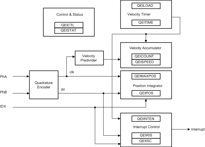
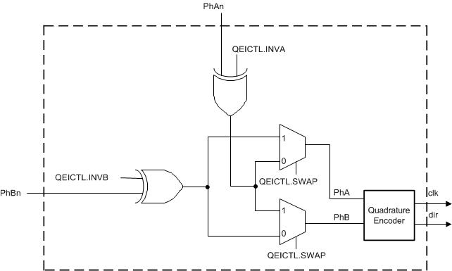
Figure 24-1 shows the internal block diagram of a QEI module. The PhA and PhB inputs shown in Figure 24-1 are the internal signals that enter the Quadrature Encoder after the external signals, PhAn and PhBn, have passed through inversion and swapping logic, shown in Figure 24-2. The QEI module has the option of inverting and/or swapping the incoming signals.
NOTE
Any references in this chapter to PhA and PhB refer to the internal PhA and PhB inputs that enter the Quadrature Encoder after the external signals, PhAn and PhBn, have passed through inversion and swapping logic that is enabled through the QEI Control (QEICTL) register.
 Figure 24-1 QEI Block Diagram
 Figure 24-2 shows the logic that is provided to allow the PhAn and PhBn signals to be inverted and/or swapped.
 Figure 24-2 QEI Input Signal Logic