SLAU723A October 2017 – October 2018 MSP432E401Y , MSP432E411Y
- 1
- 7
- 65
- 132
-
167
- 168
-
215
- 216
- 217
- 218
- 219
- 220
- 221
- 222
- 223
- 224
- 225
- 226
- 227
- 228
- 229
- 230
- 231
- 232
- 233
- 234
- 235
- 236
- 237
- 238
- 239
- 240
- 241
- 242
- 243
- 244
- 245
- 246
- 247
- 248
- 249
- 250
- 251
- 252
- 253
- 254
- 255
- 256
- 257
- 258
- 259
- 260
- 261
- 262
- 263
- 264
- 265
- 266
- 267
- 268
- 269
- 270
- 271
- 272
- 273
- 274
- 275
- 276
- 277
- 278
- 279
- 280
- 281
- 282
- 283
- 284
- 285
- 286
- 287
- 288
- 289
- 290
- 291
- 292
- 293
- 294
- 295
- 296
- 297
- 298
- 299
- 300
- 301
- 302
- 303
- 304
- 305
- 306
- 307
- 308
- 309
- 310
- 311
- 312
- 313
- 314
- 315
- 316
- 317
- 318
- 319
- 320
- 321
- 322
- 323
- 324
- 325
- 326
- 327
- 328
- 329
- 330
- 331
- 332
- 333
- 334
- 335
- 336
- 337
- 338
- 339
- 340
- 341
- 342
- 343
- 344
- 345
- 346
- 347
- 348
- 349
- 350
- 351
- 352
- 353
- 354
- 355
- 356
- 357
- 358
- 359
- 360
- 361
- 362
- 363
- 364
- 365
- 366
- 367
- 368
- 369
- 370
- 371
- 372
- 373
- 374
- 375
- 376
- 377
- 378
- 379
- 380
- 381
- 382
- 383
- 384
- 385
- 386
- 387
- 388
- 389
- 390
- 391
- 392
- 393
- 394
- 395
- 396
- 397
- 398
- 399
- 400
- 401
- 402
- 403
- 404
- 405
- 406
- 408
- 415
- 482
- 564
- 643
- 715
- 791
- 841
- 855
- 870
-
917
- 918
- 919
- 920
- 1002
- 1017
-
1021
- 1022
- 1023
- 1024
- 1025
- 1026
- 1027
- 1028
- 1029
- 1030
- 1031
- 1032
- 1033
- 1034
- 1035
- 1036
- 1037
- 1038
- 1039
- 1040
- 1041
- 1042
- 1043
- 1044
- 1045
- 1046
- 1047
- 1048
- 1049
- 1050
- 1051
- 1052
- 1053
- 1054
- 1055
- 1056
- 1057
- 1058
- 1059
- 1060
- 1061
- 1062
- 1063
- 1064
- 1065
- 1066
- 1067
- 1068
- 1069
- 1070
- 1071
- 1072
- 1073
- 1074
- 1075
- 1076
- 1077
- 1078
- 1079
- 1080
- 1081
- 1082
- 1083
- 1084
- 1085
- 1086
- 1087
- 1088
- 1089
- 1090
- 1091
- 1092
- 1093
- 1094
- 1095
- 1125
- 1189
- 1251
- 1304
- 1365
- 1431
- 1478
- 1503
- 1552
- 1569
- 1618
-
1669
- 1670
- 1671
- 1672
- 1723
-
1726
- 1727
- 1728
- 1729
- 1730
- 1731
- 1732
- 1733
- 1734
- 1735
- 1736
- 1737
- 1738
- 1739
- 1740
- 1741
- 1742
- 1743
- 1744
- 1745
- 1746
- 1747
- 1748
- 1749
- 1750
- 1751
- 1752
- 1753
- 1754
- 1755
- 1756
- 1757
- 1758
- 1759
- 1760
- 1761
- 1762
- 1763
- 1764
- 1765
- 1766
- 1767
- 1768
- 1769
- 1770
- 1771
- 1772
- 1773
- 1774
- 1775
- 1776
- 1777
- 1778
- 1779
- 1780
- 1781
- 1782
- 1783
- 1784
- 1785
- 1786
- 1787
- 1788
- 1789
- 1790
- 1791
- 1792
- 1793
- 1794
- 1795
- 1796
- 1797
- 1798
- 1799
- 1800
- 1801
- 1802
- 1803
- 1804
- 1805
- 1806
- 1833
4.1.2.4 External Reset Pin
When the external reset pin (RST) is asserted, it initiates a system reset or POR depending on what has been configured in the Reset Behavior Control (RESBEHAVCTL) Register. If the EXTRES bit field in RESBEHAVCTL is set to 0x3, a simulated full initialization begins when RST is asserted. If these bits are programmed to 0x2, a system reset is issued. When EXTRES is set to a 0x0 or 0x1, the external RST pin performs its default operation when it is asserted, which is issuing a full simulated POR.
An external reset pin (RST) that is configured to generate a POR resets the microcontroller including the core and all the on-chip peripherals. The external reset sequence is:
- The external RST pin is asserted for the duration specified by tMIN and then deasserted (see the Specifications chapter in the device-specific data sheet). This generates an internal POR signal.
- The microcontroller waits for internal POR to go inactive.
- The internal reset is released and the core executes a full initialization of the device.
- When initialization is complete, the core loads from memory the initial stack pointer, the initial program counter, and the first instruction designated by the program counter
- Execution begins.
An external RST pin that is configured to generate a system reset will reset the microcontroller including the core and all the on-chip peripherals. The external reset sequence is:
- The external reset pin (RST) is asserted for the duration specified by tMIN and then deasserted (see the Specifications section in the device-specific data sheet).
- The internal reset is released and the core loads from memory the initial stack pointer, the initial program counter, and the first instruction designated by the program counter.
- Execution begins.
NOTE
Make the trace for the RST signal as short as possible. Place any components connected to the RST signal as close as possible to the microcontroller.
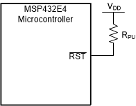
If the application only uses the internal POR circuit, the RST input must be connected to the power supply (VDD) through an optional pullup resistor (0 to 100 kΩ) (see Figure 4-1). The RST input has filtering that requires a minimum pulse duration for the reset pulse to be recognized (see the device-specific data sheet).
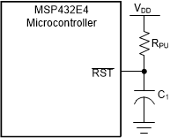
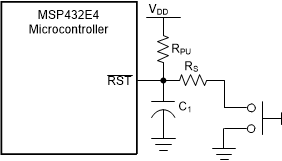
To improve noise immunity or to delay reset at power up, the RST input can be connected to an RC network (see Figure 4-2). If the application requires the use of an external reset switch, Figure 4-3 shows the proper circuitry. In the figures, the RPU and C1 components define the power-on delay.


