SLAU723A October 2017 – October 2018 MSP432E401Y , MSP432E411Y
- 1
- 7
- 65
- 132
-
167
- 168
-
215
- 216
- 217
- 218
- 219
- 220
- 221
- 222
- 223
- 224
- 225
- 226
- 227
- 228
- 229
- 230
- 231
- 232
- 233
- 234
- 235
- 236
- 237
- 238
- 239
- 240
- 241
- 242
- 243
- 244
- 245
- 246
- 247
- 248
- 249
- 250
- 251
- 252
- 253
- 254
- 255
- 256
- 257
- 258
- 259
- 260
- 261
- 262
- 263
- 264
- 265
- 266
- 267
- 268
- 269
- 270
- 271
- 272
- 273
- 274
- 275
- 276
- 277
- 278
- 279
- 280
- 281
- 282
- 283
- 284
- 285
- 286
- 287
- 288
- 289
- 290
- 291
- 292
- 293
- 294
- 295
- 296
- 297
- 298
- 299
- 300
- 301
- 302
- 303
- 304
- 305
- 306
- 307
- 308
- 309
- 310
- 311
- 312
- 313
- 314
- 315
- 316
- 317
- 318
- 319
- 320
- 321
- 322
- 323
- 324
- 325
- 326
- 327
- 328
- 329
- 330
- 331
- 332
- 333
- 334
- 335
- 336
- 337
- 338
- 339
- 340
- 341
- 342
- 343
- 344
- 345
- 346
- 347
- 348
- 349
- 350
- 351
- 352
- 353
- 354
- 355
- 356
- 357
- 358
- 359
- 360
- 361
- 362
- 363
- 364
- 365
- 366
- 367
- 368
- 369
- 370
- 371
- 372
- 373
- 374
- 375
- 376
- 377
- 378
- 379
- 380
- 381
- 382
- 383
- 384
- 385
- 386
- 387
- 388
- 389
- 390
- 391
- 392
- 393
- 394
- 395
- 396
- 397
- 398
- 399
- 400
- 401
- 402
- 403
- 404
- 405
- 406
- 408
- 415
- 482
- 564
- 643
- 715
- 791
- 841
- 855
- 870
-
917
- 918
- 919
- 920
- 1002
- 1017
-
1021
- 1022
- 1023
- 1024
- 1025
- 1026
- 1027
- 1028
- 1029
- 1030
- 1031
- 1032
- 1033
- 1034
- 1035
- 1036
- 1037
- 1038
- 1039
- 1040
- 1041
- 1042
- 1043
- 1044
- 1045
- 1046
- 1047
- 1048
- 1049
- 1050
- 1051
- 1052
- 1053
- 1054
- 1055
- 1056
- 1057
- 1058
- 1059
- 1060
- 1061
- 1062
- 1063
- 1064
- 1065
- 1066
- 1067
- 1068
- 1069
- 1070
- 1071
- 1072
- 1073
- 1074
- 1075
- 1076
- 1077
- 1078
- 1079
- 1080
- 1081
- 1082
- 1083
- 1084
- 1085
- 1086
- 1087
- 1088
- 1089
- 1090
- 1091
- 1092
- 1093
- 1094
- 1095
- 1125
- 1189
- 1251
- 1304
- 1365
- 1431
- 1478
- 1503
- 1552
- 1569
- 1618
-
1669
- 1670
- 1671
- 1672
- 1723
-
1726
- 1727
- 1728
- 1729
- 1730
- 1731
- 1732
- 1733
- 1734
- 1735
- 1736
- 1737
- 1738
- 1739
- 1740
- 1741
- 1742
- 1743
- 1744
- 1745
- 1746
- 1747
- 1748
- 1749
- 1750
- 1751
- 1752
- 1753
- 1754
- 1755
- 1756
- 1757
- 1758
- 1759
- 1760
- 1761
- 1762
- 1763
- 1764
- 1765
- 1766
- 1767
- 1768
- 1769
- 1770
- 1771
- 1772
- 1773
- 1774
- 1775
- 1776
- 1777
- 1778
- 1779
- 1780
- 1781
- 1782
- 1783
- 1784
- 1785
- 1786
- 1787
- 1788
- 1789
- 1790
- 1791
- 1792
- 1793
- 1794
- 1795
- 1796
- 1797
- 1798
- 1799
- 1800
- 1801
- 1802
- 1803
- 1804
- 1805
- 1806
- 1833
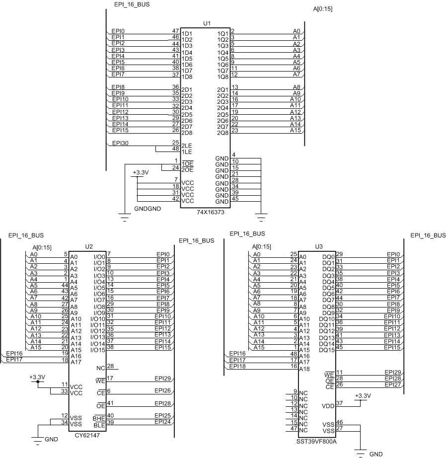
16.4.3.3 Host Bus 16-Bit Muxed Interface
Figure 16-11 shows how to connect the EPI signals to a 16-bit SRAM and a 16-bit flash memory with muxed address and memory using byte selects and dual chip selects with ALE. This schematic is just an example of how to connect the signals; timing and loading have not been analyzed. In addition, not all bypass capacitors are shown.
 Figure 16-11 Example Schematic for Muxed Host-Bus 16 Mode