SLAU748B October 2017 – September 2018 MSP432E401Y
-
SimpleLinkrep%#8482; Ethernet MSP432E401Y Microcontroller LaunchPad™ Development Kit (MSP-EXP432E401Y)
- Trademarks
- 1 Board Overview
- 2 Hardware Description
- 3 Software Development
- 4 PCB Schematics
- Revision History
2.1.7 Serial Bootloader
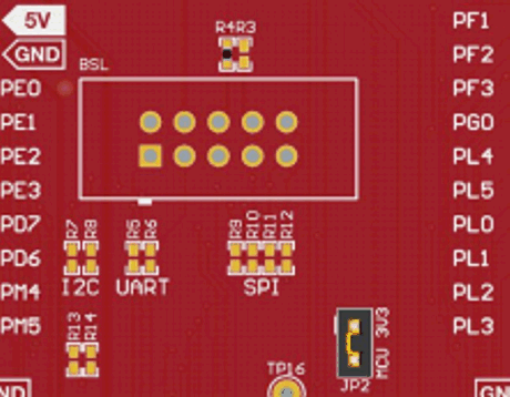
The Ethernet LaunchPad development kit enables the serial boot loader on the MSP432E401Y through the BSL header for connecting to an external BSL host interface, such as the BSL Rocket. The BSL header supports three communication protocols to the serial boot loader: SPI, UART, and I2C. To use the serial bootloader, a shrouded 100mil header (such as the AWHW-10G-0202-T from Assman WSW) should be soldered into the top side of the PCB, paying careful attention to make sure pin 1 of the connector lines up to pin one of the PCB (denoted by a square pad).
Because several of the pins for different communication protocols are shared on the header, the Ethernet LaunchPad development kit enables support for all three protocols by using 0-Ω resistor bridges for each of the signals. See Figure 4 for the location of the header and resistors on the PCB. To connect a specific protocol, populate the designated resistors with 0-Ω resistors and remove the resistors for the others protocols (see Table 6). When using I2C, populate R13 and R14 with the pullup resistors if no I2C pullups are on the external host. Typically the I2C pullup resistors should be 3.3 kΩ.
 Figure 4. BSL Header and Resistors
 Table 6. Resistors for Serial Bootloader Protocols
| Serial Bootloader Protocol | Resistors Populated With 0-Ω Resistors | Resistors Left Unpopulated |
|---|---|---|
| I2C | R7
R8 |
R5
R6 R9 R10 R11 R12 |
| UART | R5
R6 |
R7
R8 R9 R10 R11 R12 |
| SPI | R9
R10 R11 R12 |
R5
R6 R7 R8 |