SLDU028A January 2018 – March 2020 TPS65313-Q1
-
TPS65313-EVM User’s Guide
- Trademarks
- 1 TPS65313-EVM Top View With Basic External Connections
- 2 TPS65313-EVM Input, Output Voltages, and Load Current Requirements
- 3 TPS65313-EVM Jumper Settings
- 4 TPS65313-EVM GUI Installing and Opening the GUI
- 5 TPS65313-EVM Power-Up and Power-Down Procedure
- 6 TPS65313 GUI
- 7 TPS65313-EVM Typical Plots
- 8 TPS65313-EVM Schematic Diagram
- 9 TPS65313-EVM Part List
- 10 PCB Layer Diagram
- 11 Description of the Watchdog Algorithm Implemented on EVM
- Revision History
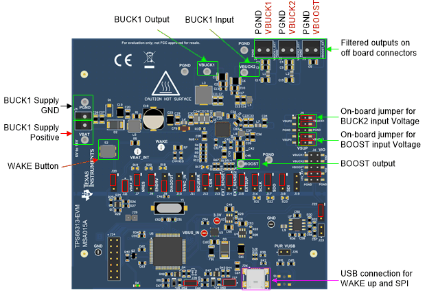
1 TPS65313-EVM Top View With Basic External Connections
Figure 1 shows the top-view diagram of the EVM along with basic connections. The BUCK1 input supply and an optional USB cable (for SPI communication) are the only two external connections required for this EVM. The BUCK2 regulator and BOOST converter are supplied through onboard jumper connections from the BUCK1 output and therefore no external supply voltage is required for the BUCK2 regulator and BOOST converter.
