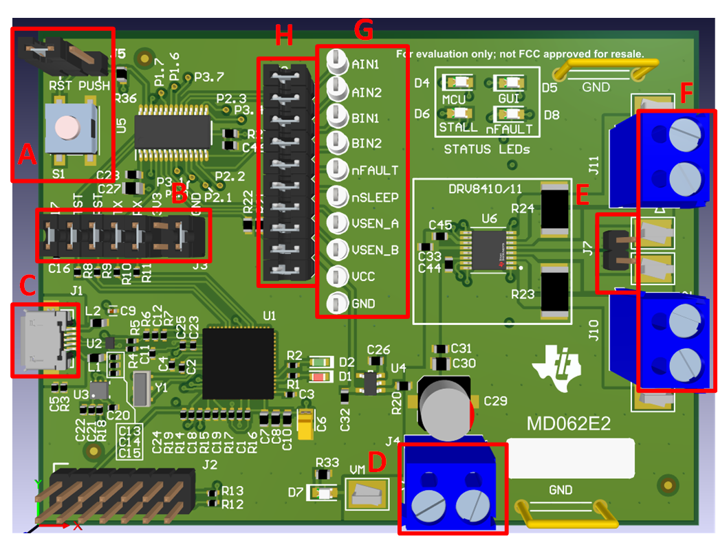
A | - J5: Sets action of push button (S1)
- RST: MCU reset
- PUSH: Debug and testing purpose (NOT used in this EVM)
- S1: Push button
|
B | - J3: Connector between eZ-FET-Lite and MSP430G2553 (U5)
|
C | - J1: Micro USB 2.0 connector
|
D | |
E | - J7: Connects AISEN and BISEN when operating in parallel h-bridge mode.
|
F | - J10: AOUT1 and AOUT2 connector
- J11: BOUT1 and BOUT2 connector
|
G | - Test points for control input signals and other feedback signals going to the MCU (U5).
|
H | - J9: Header connecting signals from DRV and other feedback signals to the MCU. Remove the shunts in order to use an external signal or MCU.
|
I |
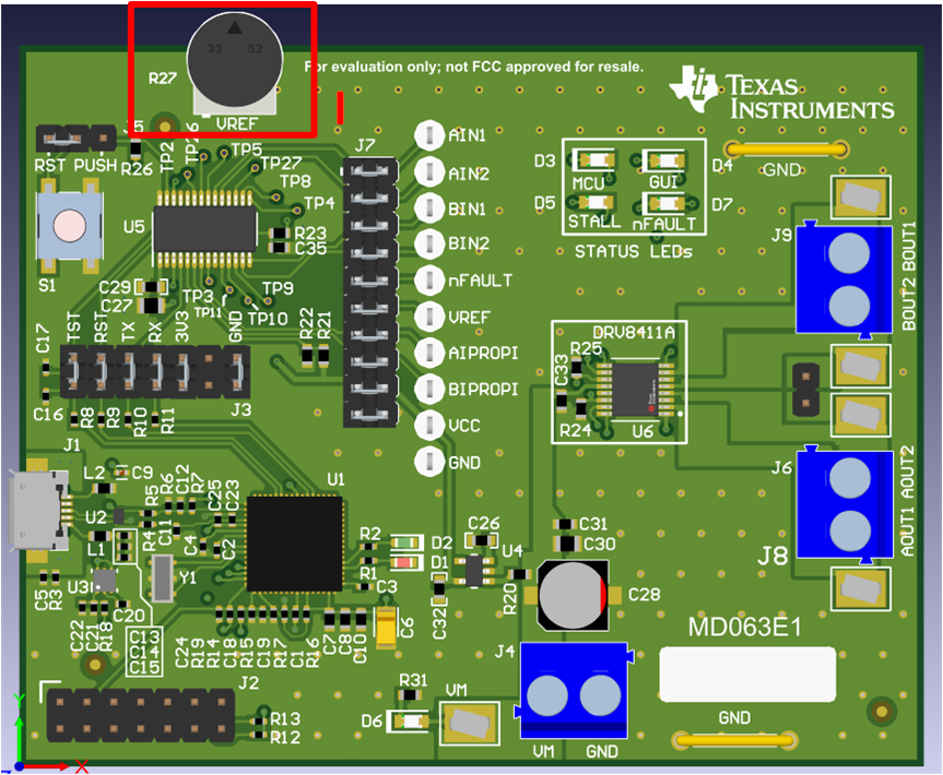
- R27: Potentiometer for setting VREF voltage.
|