SLLA498 October 2020
4.5 Dual Active Bridge (DAB)
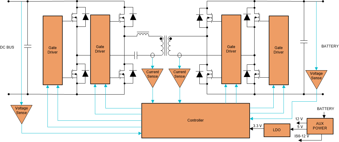
Figure 4-5 shows the basic topology of the Dual Active Bridge converter. It consists of full bridge with active switches on both the primary and secondary sides connected together by a high frequency transformer. Because of the inherent lagging current in one of the bridges, the current discharges the output capacitance of switches of one bridge (say, the secondary side) and some switches of the primary side thereby enabling ZVS turn on. In addition to this lossless capacitive snubbers can be used across the switches to reduce turn off losses. The main advantages of this converter are its inherent bidirectional capability which is achieved by controlling the phase angle between the two bridges and its modularity that allows it to be scaled to higher power levels.

Figure 4-5 Dual-active Bridge Converter
The control scheme of the DAB ranges from simple (or single phase shift modulation) to complex (for extended, dual and triple phase shift modulation). This topology can be used to cover wide variation of battery voltages with single phase shift modulation but circulating currents in the transformer increase which drastically reduces efficiency. But with advanced modulation schemes like triple phase shift, the converter can theoretically achieve ZVS efficiently over the entire operating range. Since transformer utilization is high for this topology, the size of transformer required to deliver same amount of output power is relatively smaller. The output capacitor needed to handle the ripple current is also low for this converter. This converter with relatively fewer number of devices, soft-switching commutations, low cost, and high efficiency is used in applications where the power density, cost, weight, isolation and reliability are critical factors. One limiting feature is that the converter often requires an additional shim inductor which is needed for tuning ZVS operation that can make the converter bulky.
The TI reference design Bi-directional, dual active bridge reference design for level 3 electric vehicle charging stations contains details on the implementation of this converter. This topology being a bidirectional DC/DC topology, can be used for the bidirectional DC/DC stage (see Figure 3-1) between the Battery Management System and HV DC Bus.