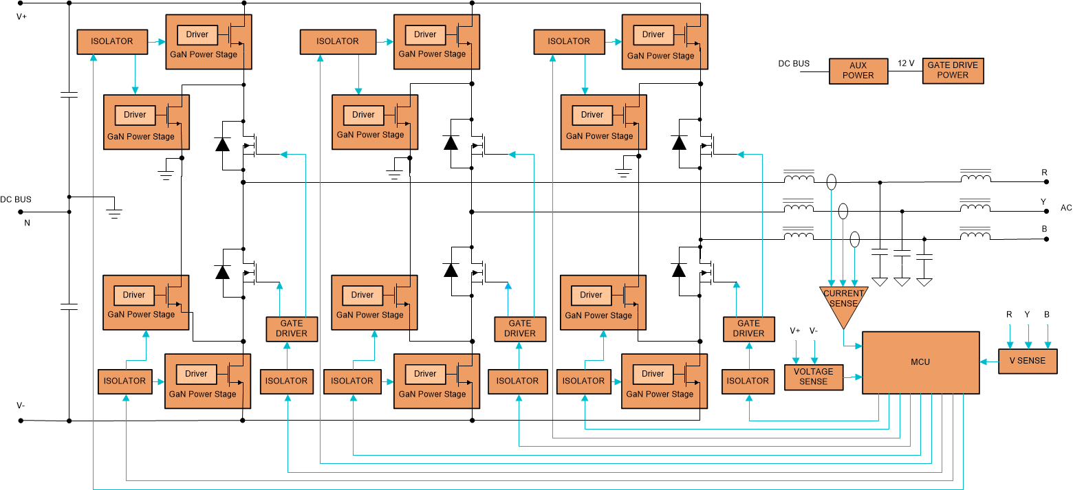
The Active Neutral Point Clamped (ANPC) inverter is an improved version of the NPC inverter, in which the diodes of the NPC topology are replaced with active switches as shown in Figure 5-5. We get a more uniform loss distribution because of this, making thermal management a lot easier. Also with reduced blocking voltage across all switches, Gallium Nitride (GaN) switches can be used in this topology which improves efficiency and power density of the converter. It is the most suitable topology for high-frequency switching because of the comparatively lower switching losses.
The major drawback of this topology is the number of controlled switches to be addressed. In a three phase application, a total of 18 switches are required to be controlled by individual PWMs. Use of advanced smart switching schemes can help reduce the number of PWMs to a third, if implemented wisely. Each of the 18 switches would also need a gate driver, and that could also be cut to half by use of dual-channel gate drivers. This topology makes up for the complexity in its implementation by improved power density, higher efficiency as well as overall reduced system cost that comes from design of smaller size magnetics/passive components and fewer cooling needs. This bidirectional DC/AC topology is an option to consider for the bidirectional DC/AC stage (see
Figure 3-1) between the HV DC Bus and the AC Bus in a storage ready solar inverters.
 Figure 5-5 Active Neutral Point Clamped (ANPC) Inverter.