SLLA498 October 2020
4.1 Synchronous and Interleaved Boost Converter
The boost converter is one of the basic converter topologies and quite simple to implement. It needs only one controlled switch (MOSFET, IGBT, and so forth) and an uncontrolled switch (diode) along with an inductor to realize it. The efficiency also is quite high if it is designed well, due to fewer components. At higher power levels, the diode is replaced by another controlled switch (used as a synchronous switch) to reduce conduction losses. Thus it becomes the synchronous boost converter.
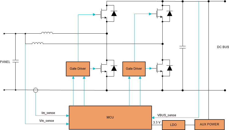
With even higher power levels (as encountered in string inverters), we end up paralleling the power devices so as to reduce conduction losses. However, paralleling the devices does not help with the increased ripple currents. So multiple stages of synchronous boost converters are used with phase-interleaved PWMs driving each converter. For ‘n’ number of interleaved stages, the phase difference between the individual PWMs is 360o/n. This significantly reduces ripple currents and helps reduce the overall size. The efficiency as well as thermal loss distribution also gets improved compared to single- or paralleled-power stages. Figure 4-1 shows a two-phase interleaved boost topology. For more detailed analysis of this topology, see Under the Hood of a Multiphase Synchronous Rectified Boost Converter White Paper.
 Figure 4-1 Two-phase Interleaved Boost Topology.
 A typical solar MPPT DC/DC power stage implementation using interleaved boost converter is discussed in the Digitally Controlled HV Solar MPPT DC-DC Converter Using C2000™ Piccolo™ Microcontroller Application Report. This topology being a unidirectional DC/DC topology is an option to consider for the DC/DC stage (see Figure 3-1) between the solar panels and HV DC Bus.