SLLA565 September   2021 TUSB1044


  1.   Trademarks
  2. 1Introduction
  3. 2TUSB1044 Configuration and Control Implementation
    1. 2.1 TUSB1044 Four-Level Pins
      1. 2.1.1 I2C_EN
      2. 2.1.2 VIO_SEL
      3. 2.1.3 UEQ[1:0] and DEQ[1:0]
      4. 2.1.4 CFG[1:0]
    2. 2.2 TUSB1044 Two-Level Pins
      1. 2.2.1 FLIP, CTL0, and CTL1
      2. 2.2.2 DIR0 and DIR1
      3. 2.2.3 SWAP
      4. 2.2.4 HPDIN
      5. 2.2.5 SLP_S0#
  4. 3TUSB1044 I2C Mode Implementation
    1. 3.1 TUSB1044 Operating Mode Configuration, General_1 Register, 0x0A
    2. 3.2 VOD Configuration, General_3 Register 0x0C
    3. 3.3 Upstream and Downstream Equalization Configuration Registers, UFP1_EQ, UFP2_EQ, DFP1_EQ, and DFP2_EQ Registers 0x10, 0x11, 0x20, 0x21
  5. 4Benefits of Using the I2C Mode Control
  6. 5TUSB1044 Host Implementation Example
  7. 6TPS6598X, TPS6599X Based I2C Control and Tuning
    1. 6.1 Enable PD Controller I2C Control of External Slaves
    2. 6.2 Example of I2C Configuration Upon PD Controller PoR Event and Detach Event
    3. 6.3 Example of I2C Configuration Upon Cable-Orientation Event and DP Configuration Event
    4. 6.4 Notes for Application
  8. 7References

Notes for Application

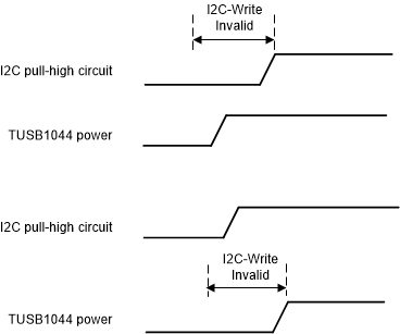
If the power on event is selected to be the trigger event to initiate the EQ, VOD, and DCGain configuration to TUSB1044, it is important to pay attention to the power sequence of the TUSB1044 and I2C pull-high power rail. A later power on or not stable of pull-high power rail may lead to concern of not successfully setting the TUSB1044. Under these conditions, it helps to use the attach event to trigger the config to 0x10, 0x11, 0x20, 0x21, and 0x0C to secure the successful configuration to the redriver.

GUID-20210713-CA0I-5BXM-661V-2DVWCXLHSGV3-low.gif

Figure 6-5 Example of Invalid I2C Write Region

GUID-20210707-CA0I-TPDK-SZRC-1NMLQLW2SNRK-low.png

Figure 6-6 Example of TUSB1044 Re-config Upon Attach Event

Figure 6-7 shows where the data sheet required items to achieve lower power consumption in shut down mode.


GUID-20210707-CA0I-1KGN-G4SD-LBWVNTTCZNSC-low.png

Figure 6-7 Power Consumption Information

There is a special notice on the conditions to achieve lower power consumption for a certain shutdown or sleep mode of the system, that CTL1, CTL0, and I2C_EN = 0. It indicates that a special pull-high power rail design for the three IOs to achieve shutdown mode power of TUSB1044 must be considered in the design, especially when I2C control is enabled (pull high I2C_EN).