SLLA590 May 2022 THVD8000 , THVD8010
- Abstract
- Trademarks
- 1Introduction
-
2THVD80x0 Devices Theory of Operation and
Limitations of Use
- 2.1 Overview and Similarities between Standard RS-485 Transceivers and THVD80xo Devices
- 2.2 Differences between Standard RS-485 Transceivers and THVD8000/8010
- 2.3 Standard Approach to Using THVD80xo Devices to Communicate over Power Lines
- 2.4 Drawbacks to Standard Approach with Higher Voltage Systems
- 3Integration of Line Driver with THVD80x0 Devices to Drive Low Impedance Loads
- 4High Voltage Interface and Communication Interface Power Supply
- 5System Level View and Relation to Higher Voltage Implementations
- 6Summary
- 7References
2.3 Standard Approach to Using THVD80xo Devices to Communicate over Power Lines
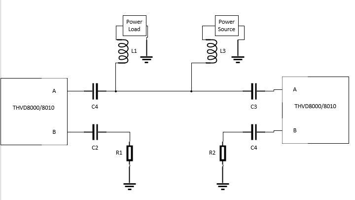
When interfacing the THVD8000/8010 to a power line the general idea is very straightforward – couple the data signal into the power signal and ensure that the data can be recovered at the other end without exposing the THVD8000/8010 to dangerous high voltages. This is done by adding series capacitors to the A and B lines for each transceiver while protecting the power supply and power load with inductors. The basic differential setup is shown below in Figure 2-2 and a basic single ended setup is shown in Figure 2-3.
 Figure 2-3 Standard Approach to Powerline
Communication with THVD80x0 in Pseud0-Differntial Mode
Figure 2-3 Standard Approach to Powerline
Communication with THVD80x0 in Pseud0-Differntial ModeBoth single ended and differential implementations use the same formulas for capacitors and inductors. The capacitors should have an impedance magnitude of 5 Ω or less at the OOK modulation frequency to minimize attenuation of the data signal. The inductors are treated as a component from either the A or B line to AC ground, even in instances where the power signal is AC. This assumption can be made as the system under normal operating conditions operates in a linear manner allowing the principle of super-position to hold when sizing inductors. The total impedance magnitude of all inductors in parallel needs to be 375 Ω or more to ensure proper communication thresholds are reached at the RX side of the power line. The 375 Ω parameter comes from the RS-485 standard which allows 32 unit loads in parallel on the same line with each of those 32 units loads having a minimum input impedance of 12K Ω. At 32 unit loads in parallel the effective impedance to ground is 375 Ω per line, which is 12K Ω / 32. By sizing the capacitors and inductors this way most high frequency energy will be delivered from TX to RX while the power signal’s energy mainly stays on the power line and is routed through the inductors. For reference on lower voltage power line communication using the THVD8000 please see the THVD8000 Design Guide.
However, for higher voltage and lower impedance power systems, this method has a few drawbacks that make this type of implementation not a valid solution.