SLLA590 May 2022 THVD8000 , THVD8010
- Abstract
- Trademarks
- 1Introduction
-
2THVD80x0 Devices Theory of Operation and
Limitations of Use
- 2.1 Overview and Similarities between Standard RS-485 Transceivers and THVD80xo Devices
- 2.2 Differences between Standard RS-485 Transceivers and THVD8000/8010
- 2.3 Standard Approach to Using THVD80xo Devices to Communicate over Power Lines
- 2.4 Drawbacks to Standard Approach with Higher Voltage Systems
- 3Integration of Line Driver with THVD80x0 Devices to Drive Low Impedance Loads
- 4High Voltage Interface and Communication Interface Power Supply
- 5System Level View and Relation to Higher Voltage Implementations
- 6Summary
- 7References
2.1 Overview and Similarities between Standard RS-485 Transceivers and THVD80xo Devices
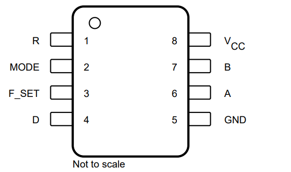
The THVD8000 and 8010 are RS-485 compliant transceivers that use OOK modulation on the input data to transmit data across a power line. This converts a logic 0 into a pulse train with a pre-selected frequency and a logic 1 into a flat output (V_B – V_A ~0V). Due to this part’s added features the pinout is different from a standard half duplex RS-485 device; a pinout is shown in Figure 2-1 for both devices.
 Figure 2-1 THVD80x0 Pinout
The similarities between a standard RS-485 half duplex transceiver and the THVD8000 and THVD8010 parts can be seen in Figure 2-1. Pins 1, 4, 5, and 8 remain similar across most RS-485 devices. Pins 8 and 5 are the power connections to the IC, while pins 1 and 4 are the single ended RX output and TX inputs respectively. The B and A pins are still used for differential communication as in other RS-485 devices and still conform to the 1.5 V differential voltage over a 54 Ω; however, the A/B pins use OOK modulation instead of a typical pulse train used in RS-485.