SLLA593 August 2022 TUSB211 , TUSB212 , TUSB216 , TUSB216I , TUSB217A
3 Device Mode Testing
In device mode testing, enumeration of the USB device sending high-speed test packets is required. In order to support this enumeration, observe the device test packets, and provide bus power for the device. The use of a relay or switching board is necessary. The board allows the enumeration and test packet command to travel from the host to the device, while also allowing the test packets to be observed without any reflections or interference from upstream. Relay boards are included in any typical USB 2.0 approved test fixture.
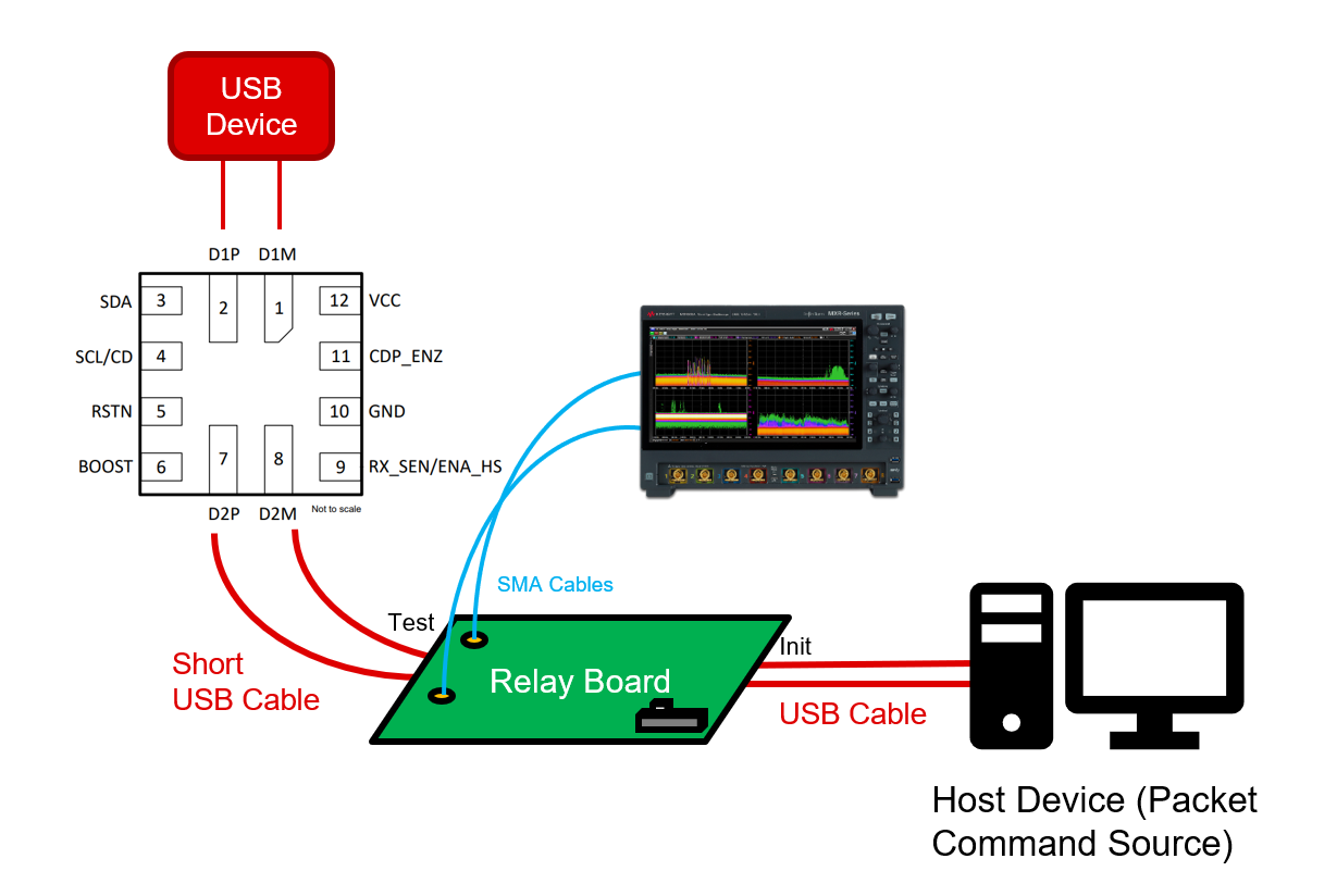
A basic system diagram for device mode testing is shown in Figure 3-1. A host device, the source of the test packet command, is connected to the "init" port of a test fixture relay board. As with host mode testing, the test host must be a Windows device capable of running the USB-IF HSET software. The "test" port of the relay board is connected to the TUSB21XX's input via a short USB cable. An oscilloscope is connected to the DP/DM data lines on the relay board via SMA cables. Finally, the USB device is connected on the output of the TUSB21XX device.
 Figure 3-1 Device Mode Test Setup