SLLA593 August 2022 TUSB211 , TUSB212 , TUSB216 , TUSB216I , TUSB217A
4 Embedded Host Mode Testing
When performing testing in embedded host mode, a specialized PID/VID device is required in addition to a relay or switching board as used in device mode testing. The device must present a specific PID/VID combination which upon enumeration will set the embedded host into test mode. The desired VID for embedded testing is 0x1A0A. The PIDs are arranged by test type and are summarized in Table 4-1. For high-speed signal quality testing, the desired PID is 0x0104 (TEST_PACKET).
| PID | Test Type |
|---|---|
| 0x0101 | TEST_SE0_NAK |
| 0x0102 | TEST_J |
| 0x0103 | TEST_K |
| 0x0104 | TEST_PACKET |
| 0x0105 | RESERVED |
| 0x0106 | HS_HOST_PORT_SUSPEND_RESUME |
| 0x0107 | SINGLE_STEP_GET_DEV_DESC |
| 0x0108 | SINGLE_STEP_SET_FEATURE |
| 0x0200 | TTST_CONFIG |
| 0x0201 | Unknown Device Not Supporting HNP |
| 0x0202 | Unknown Device Supporting HNP |
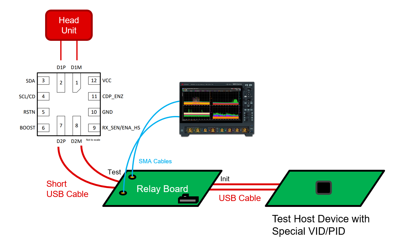
An example system setup is shown in Figure 4-1. The VID/PID device is connected to the "init" port of a test fixture relay board. The "test" port of the relay board is connected to the TUSB21XX's input via a short cable. An oscilloscope is connected via SMA cables to the DP/DM data lines on the relay board. Lastly, the head unit or "embedded host" is connected to the output of the TUSB21XX through some means of connection, such as cabling or trace routing within a PCB.
 Figure 4-1 Embedded Host Mode Test
Setup